* GadgetBuilder.com *
Last Modified:
Click to Enlarge
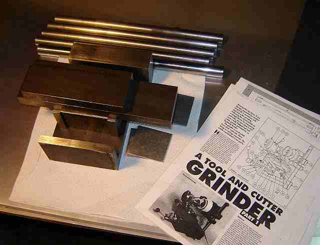
I eventually returned to my old notion of building a Brooks-Stent (the plans disappeared from Yahoo! Groups in January '07 -- after I copied them to my disk :-) to sharpen end mills. As usual when starting a project, it looks like it addresses most of my concerns. Except easily gashing end mills - but I found a simple mod allows gashing. Gashing is a peculiar subject, I rarely see it mentioned in descriptions of sharpening cutters in the home shop yet it was an obvious problem when attempting to sharpen a blitzed cutter with the Mini-Tinker.
Conceptually, the Brooks-Stent is a surface grinder with a very small work envelope and table X-Y controls appropriate for cutter grinding; work heads and fixtures are mounted to the movable table to orient cutters for grinding.
I found some minor errata to the published plans and noted the description of sharpening the helix is likely theoretical since the hole to hold the locating finger isn't present in the pictures of the actual unit. Sharpening the helix is better done using a separate work head as described here. A separate adapter is needed for slitting saws. Many pictures in this section are shown smaller (not thumbnails, so the full size is always loaded into your browser) and can be clicked to see the full size version.
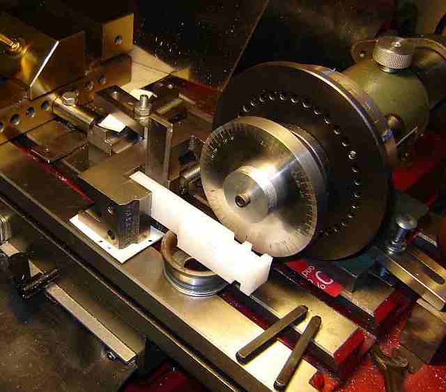
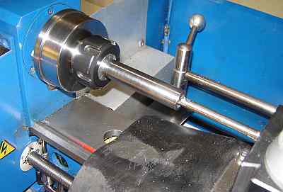
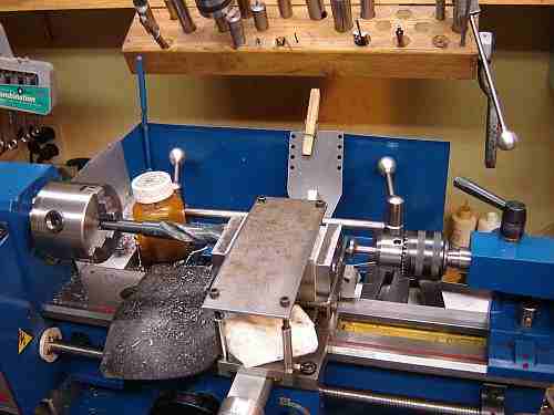 The first task was to make a metal "sandwich" from the center slide and the pieces which will support the movable table, drill two 11/16" parallel holes, line bore them to 0.740" (to ensure the holes are precisely parallel) and ream to 0.750" so they accept the 3/4" ground rods. The sandwich is held together with a small screw on each end plus the simple clamp built for this purpose; the sandwich is lightly clamped to the cross slide, set precisely parallel to the ways, and the clamp tightened. My cross slide had two holes on the far end for the taper attachment and one on the near end to hold the Y DRO so only one hole had to be added to accommodate the clamp. Drilling was done by starting with 1/8" and stepping up to 11/16", using the pusher shown in the tailstock to advance the carriage rather than the carriage handwheel - this keeps the force in line with the bit to minimize swiveling of the carriage.
 The boring bar shown is from a discarded line printer. The cutter is 1/8" drill rod, shaped then hardened and sharpened; the cutter is held in place with a 6-32 setscrew. The cutter was rotated so it had a side rake of about 30 degrees; this cut nicely but the chips formed long, tight curls as seen in the picture. The cutter depth was set using a J tool per Dave Gingery and supplied by Richard Hagenbuch; this allows increasing the diameter fairly precisely using a gap gauge. The bolt opposing the J locks the tool to the bar with the other bolt over the cutter; a gap gauge set to the desired change is captured between this bolt and the cutter, the gauge removed and the cutter advanced to touch the bolt - simple and effective. The J tool and the 3/4" expansion reamer are shown in the picture below, along with the partially complete main block. The expansion reamer was ideal for this task, allowing the hole size to be adjusted nicely to fit the rod.
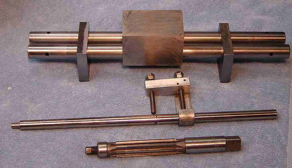
The center slide is shown inverted above. Eventually, the two smaller pieces will support the movable table. In this picture the table supports are holding the rods to allow the movement of the center slide along the rods to be evaluated. This is my first experience line boring and the result seems very nice - the block slides freely from one support to the other with no binding.
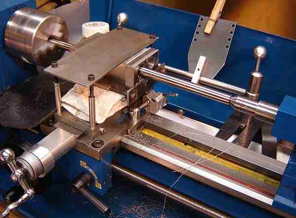
This is the process of drilling/boring the other holes (Y axis). Here, the sandwich includes the front and rear plates to support the round ways that the center block slides on. 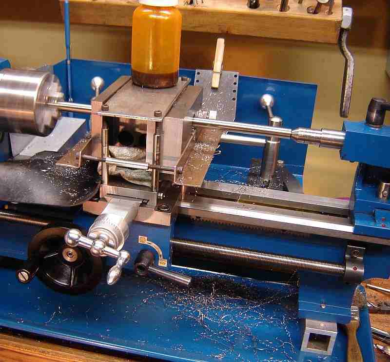 I used 0.750 ground rods that were available used for $2 each; they came from the conveyer of a large machine and had no discernible wear, plus the same local vendor had the 3/4" expandable reamer for $6 so the construction cost was quite reasonable. The previous (X axis) holes are visible in the middle of the sandwich.
I remain unsure whether the minilathe is well suited for line boring. Brooks used a Myford which is probably better suited to the task although it seems he ran into some difficulty and made some oversize holes; he suggested using a cross slide lock if it is available, a possible clue to how the holes became over size... Since the 7x12 doesn't include a CS lock, I positioned the CS and locked it by tightening the gib adjustments. I found that the rotating cutter applies a significant force in a continuously varying direction so it works on any looseness in the lathe carriage -- the rear of the carriage moved up and down slightly from the force so the resulting bore was not smooth; fortunately, the reamer handled smoothing the result. Apparently, this random roughness averaged out because both the X and Y slides work smoothly despite a very snug fit of the way rods. In addition to vertical and horizontal movement of the carriage I noted a tendency for the carriage to self-feed along the ways due to the cutting action, similar to climb milling, and this likely added to the roughness. Another detail: the force available from the clamps was constrained by the cross slide bending from the force, making it difficult to move. Overall, the 7x12 did the job but my feeling was the lathe wasn't happy doing it.
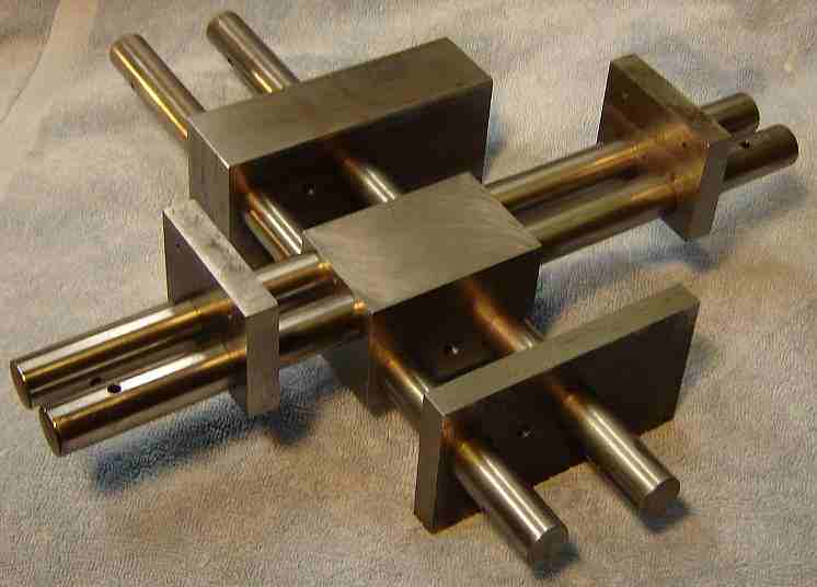
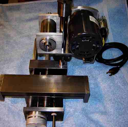
The main parts of the frame are shown above assembled for a trial fit. Making these parts was nerve wracking because of the amount of time invested -well over 20 hours - all of which could be wrecked quickly if things went awry. Additional work is needed on the leadscrew hole for the Y feed but if this goes awry it should be recoverable. Brooks directions for boring the Y holes are vague in that it is unclear whether he made the sandwich as I did (with the main block inverted) or had the main block upright with lots of packing. Since the leadscrew hole is centered between the other two holes, if there is any slight difference in the spacing it would cause a problem for me when the block is upright so I will complete this hole later with the block upright and positioned by the ways bars.
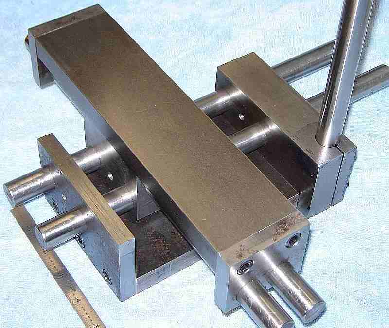
Following some drilling and tapping plus boring and slitting the hole for the motor standard, here is a trial assembly of the basic frame for the grinder. Clearly the rods have not been trimmed to length yet.
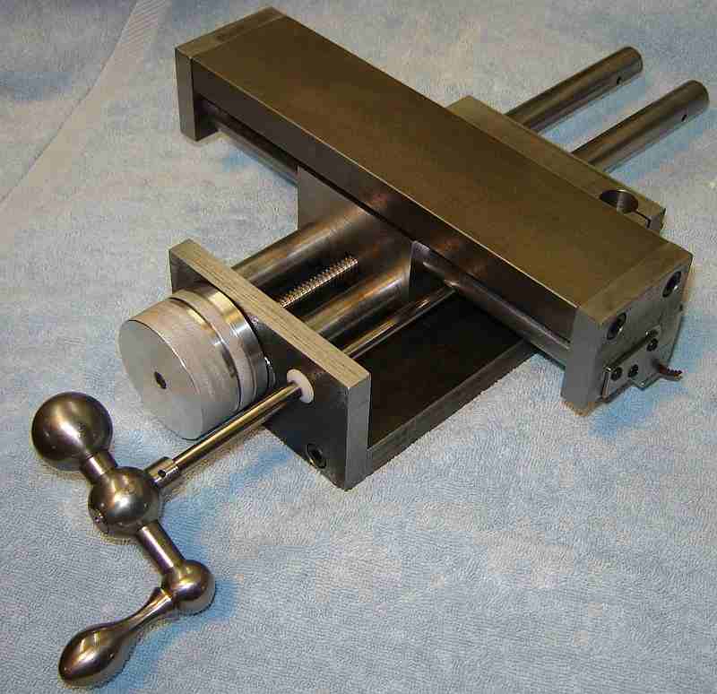
The major motions for cutter sharpening are fine feed via a lead screw to adjust the grind depth and a coarse traverse to pass the edge being sharpened past the wheel.
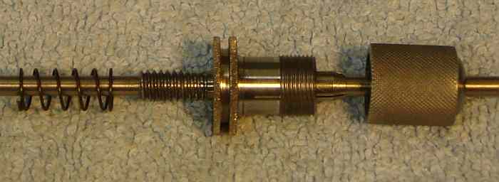
The 10 tpi lead screw was turned from 3/8" 12L14 and a 688AZ shielded ball bearing was fitted. The LS hole in the front was drilled out to 9/16 and the inside end of the hole in the front was bored to accept this bearing (about 0.630). Pre-load was added (via a simple fitting at the rear) to remove bearing backlash. The rear 0.700 of the LS hole in the center slide was opened to 0.530 and a Delrin lead nut was turned 10 tpi LH, sized to be a press fit in this hole. This seems to work well and is much easier (and cheaper) than tapping the steel center slide. Delrin is fairly low friction and is easy to replace if problems occur. LH taps are expensive but I had to make a tool to single point the nut because my smallest boring bar was too big - took over an hour so maybe a LH tap wasn't so unreasonable... Still, Brooks scheme of tapping 10 tpi in steel seems like a tough way to go. Backlash in my setup is zero through most of the travel, increasing to 2 thou for the rear inch of travel. This may increase with time as wear occurs, of course, but normal procedures for handling backlash (per Brooks) should handle this nicely. The Y DRO on my lathe was a big help in threading the lead screw and lead nut.
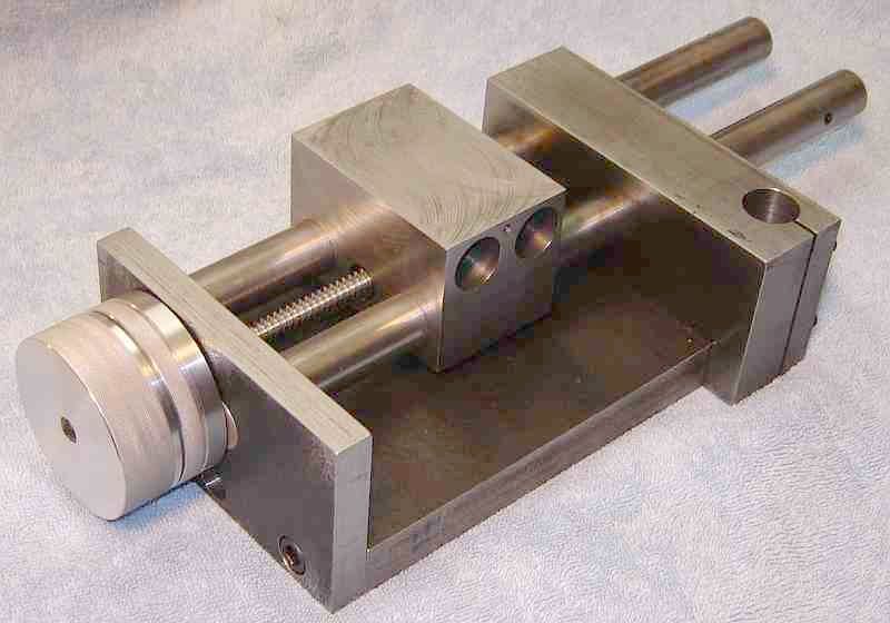 The knob for the leadscrew is 2.34" diameter, with the dial (unmarked here, it includes a knurled strip to allow adjusting vs knob/shaft position) and is friction driven by a piece of felt between the knob and dial. I made a recess in the knob to hold the felt and cut the OD of the dial down about 0.2" to allow it to enter this recess slightly to compress the felt; the felt is thus protected from grit. A sleeve over the shaft sets the distance between the bearing and the knob; this sleeve traps the bearing inner race against a shoulder on the leadscrew side while a 6-32 buttonhead in the end secures the assembly to the shaft. A shoulder on this sleeve sets clearance between the dial and the front; a felt pad here prevents grit from entering the bearing recess. Experience will determine whether a spinner handle should be added to the knob - the knob turns easily so a round depression might work well to allow rapid movement for initial positioning of the work vs the wheel.
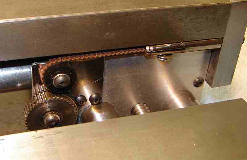 The traverse mechanism is built entirely from found material (scrap). The cog belt is from a line printer and the drive gear is from a defunct electric drill, where it happened to fit the belt perfectly although a smaller diameter gear would be preferable. The plastic idler is a gear from a VCR with the teeth removed. The tension mechanism is a small cylinder, end drilled and tapped half way through; the other end is slit to allow entry of the end of the belt and is cross drilled and tapped 6-32 for the clamp screw. A saw cut near the inside end of the slit, top and bottom, thins the material for easier clamping. The screw through the end plate is close to the bottom of the table so the cylinder is flattened to allow the screw to enter - this way a wrench isn't needed to keep it from rotating as the tension is adjusted. Lots of details for such a simple item but it works well. The tension setting isn't critical but must be set to avoid belt slack when reversing direction. The fiber reinforced printer belt has no apparent stretch so tension is easy to set. The drive gear needn't be a gear; a cog wheel could be made by gashing with a slitting saw.
 The traverse handle is another treasure from the metal pile at Newtown's dump. Like Brooks' handle, it is too large to allow rotation if it is over the bench holding the grinder. Brooks simply places the grinder near the edge of the bench so I may do the same - or add rubber feet, the handle isn't much too large. Completing the use of scrap for the traverse, the shaft is from a line printer. The shaft bushing is white Delrin.
Both the feed and traverse controls work smoothly and easily. This completes the main parts of the frame but there are many minor details to go, things like the plates that retain the felt way wipers where only one is in place now so there are 24 more 6-32 holes to drill and tap in the center block, etc.
I purchased an older lathe (Rockwell 10") in late March '07 so I put the Brooks on hold for several weeks while I got this "new" lathe moved into my shop, cleaned, painted, and repaired enough so it is usable. I found that some operations would be more easily handled on a lathe larger than the 7x12 (Brooks used a Myford) so when the Rockwell became available I decided now was the time.
 The Aux table has an arced slot with a radius of 5.125", not easily done on my 4" rotary table. So, I drilled the hole at the center of the circle and drilled a hole at each end of the arc. The arced slot was "chain milled" by positioning the cutter so it was at the center of the slot and 1/2 of the cutter diameter further along the arc; this was done by eye with a cutter smaller than the desired slot size. Then I put a pin on the mill table to fit the hole so the aux table could be pivoted around this pin. A spacer of 1/4" plywood was used between the work and the mill table to avoid marking the mill table. I used an end mill smaller than the arc width and gripped the aux table with a large clamp that acted as a handle. Maintaining a good grip on the clamp, the cutter was slowly moved along the arc by rotating the table around the pin. Cutting forces are larger than I anticipated so use caution if you use this method. The required slot width needs several passes with the small cutter to get full width. Although the method is crude, the result looks good.
The 3/4" hole in the aux table was step drilled to 11/16", opened up with the boring head to 0.742 and finally reamed to 0.750". The recess around the bottom of this hole was done in the 4 jaw chuck on my (new to me) Rockwell 10", my first use of this lathe.
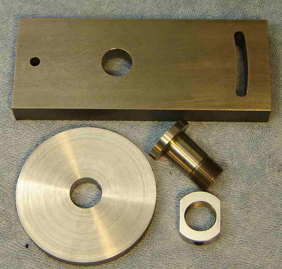 The swivel base was turned to size and faced in the Rockwell 3 jaw and parting was begun, allowing about 1/8" more than the target thickness. When the groove was about 1/2" deep the work was moved to the bandsaw to complete parting. It was then moved back to the 3 jaw and the saw marks were faced off along with the excess thickness. The center 3/4" hole was drilled and reamed in the lathe using the method described for the aux table. Degree markings remain to be added; I need to make a tool for this so it will be done later.
The bolt to secure the swivel to the aux table was turned partly in the Rockwell, then transferred to the 7x12 to finish to size and add the thread - mainly because I'm still more comfortable with my old 7x. The diameter of the bolt fits the reamed holes in the swivel and aux table nicely. The 1/4" hole through the center of the bolt was drilled under size and reamed per the directions; I don't know the function of this hole yet. The nut was turned to size and the flats milled to allow using a 15/16" open end wrench, then d/t for a 1/4-20 set screw -- this is per the plans although the pictures show a hex nut. A small piece of nylon is fitted in the set screw hole to avoid marring the threads on the big bolt.
 I built the Linerator to add graduations, then added the numbers to the swivel base with this setup. The setup is rigid enough that numbers can be re-struck accurately if needed. The slot in the piece of plastic sets the space between the 3/32" numbers when one digit is pushed left and struck then the other digit is pushed right and struck. The slot width is 0.340 and the punch body is 0.250 -- there is another slot for wider spacing plus a third slot on the other side that can be positioned on top for single digits. Each quadrant goes from 0-40-0 so I marked all the 10's positions with ink, struck them, wiped the ink off, added ink at all the 20's positions, etc. -- this to simplify things and avoid a mixup on the numbers...
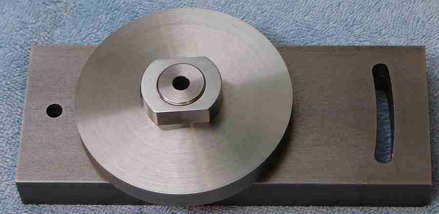
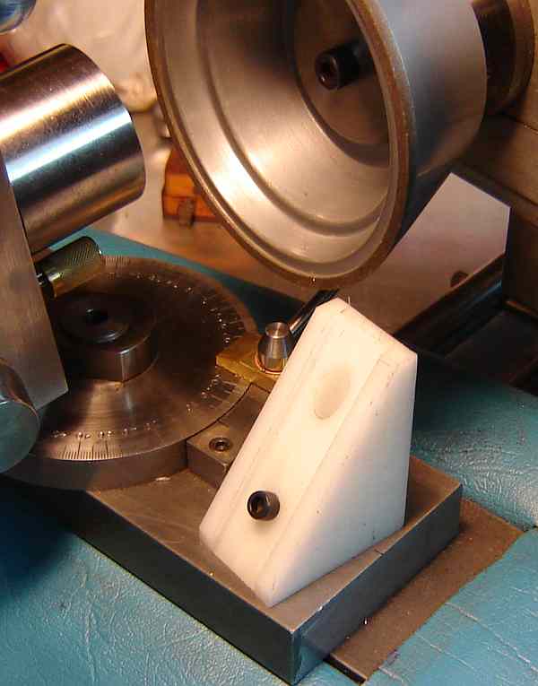
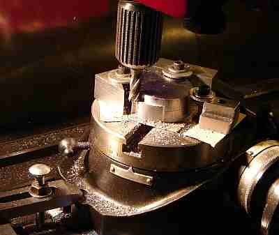 The part that mounts on the swivel base was more of a challenge than the base itself, mainly because I used the rotary table on the mill to cut part of it, as shown in the picture. Three clamps were needed to hold the part to the rotary table but one clamp had to be moved to complete cutting the necessary part of the circumference.
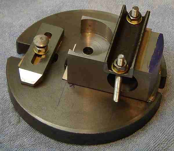 Machining the tilt head body was done on a catchplate (used as a backplate) which came with the Rockwell. This was my first use of a backplate and it went well although it took a while to figure out how to clamp it so the clamps wouldn't interfere with the needed cuts. The milling clamp on the other side is for partial balance.
 There are a number of small parts associated with the tilting head so it takes some time to complete. My toolholder accepts R8 collets and is shown here in the head. The lower handle locks the tilting head at the desired angle.
 The tilt head is beginning to look a lot like the cover picture except for the difference in collet type used to hold the cutter. The knurl on the dial didn't come out well because the 7x12 couldn't generate enough force for 316 SS -- so, I used brass for the collet nut and the knurl worked well. Both of these knurls were done with the bump knurler because they are beyond the capacity of my clamp knurler.
The tilting head side plate is needed to hold the fiducial mark for the tilt angle but the locking mechanism seems superfluous - the tilt angle is locked by the handle on the other side too...
 The spindle for the grinding wheel is based on the Broadley design often used on the Quorn. I couldn't find magneto bearings so angular contact bearings are used.
I didn't have a steady rest so I built one... this picture shows it in use on the spindle body, where the cardboard keeps chips away from the steady's rollers. The rollers polished tracks on the spindle body, visible in the picture below.
 The spindle body is 2" 12L14, ends are CRS, and the spindle is from Stressproof 1144 (variety is the spice of life); the 12L14 turned best.
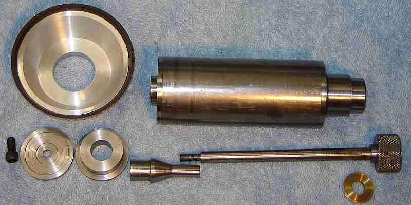
I made the adapter taper piece slightly different from the Broadley design in that I tapped the taper and threaded the drawbar. This wheel adapter accepts a wheel with a 1.25" hole, where the wheel end of the adapter is 0.625". Most wheels now have 1.25" holes but other hole sizes can be accommodated by making appropriate adapters. Each wheel needs a taper and adapter so that once mounted and trued these assemblies can be exchanged without re-truing.
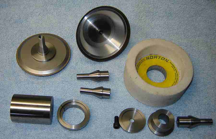 The picture shows three wheels: a narrow CBN plated wheel, an AbTec CBN composite taper cup, and a Norton AO cup. I made 5 adapters, where 3 are for the wheels shown along with two spares for additional wheels. Adapters are customized to the wheel so the raw material for additional adapters is at left. A pot chuck (shown) for use in the Rockwell's 3 jaw was made to hold the adapters for final machining because they're impossible to grip in a regular chuck. This pot chuck accommodates either piece of an adapter where the pieces can face in either direction because the chuck allows the 1.25" diameter through. This was my first use of a pot chuck; it is accurate and allows gripping thin items easily -- makes a potentially awkward operation easy.
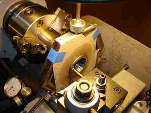
 The spindle taper for mounting wheels was cut when the spindle was turned initially. To ensure the taper runs true to its bearings I gripped the nut on the completed spindle in the chuck and held the spindle body in the steady rest, then took a truing cut along the taper. The spindle body remained stationary so it was run at higher speed than I normally use with the steady. Best guess is this wasn't really necessary since the cut was even over the circumference but this seemed a simple way to ensure the spindle runs true. It took 15 minutes of fussing to get it set up for a pass that took about 30 seconds...
The motor and spindle are mounted to a plate per the Broadley design; Brooks used a toolroom grinder and mounted the wheel directly to the motor shaft.
 My motor/spindle mount is made from scrap. Mostly aluminum plate plus a pinch block of mystery metal (some type of steel that cuts nicely); a vertical bolt hole from its previous life shows on the front facing surface.
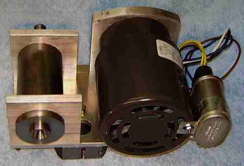
The Broadley scheme uses a jacking screw supported by a cap on the motor column (pole). I used a piece of 1/4-20 allthread for the jacking screw. The motor is a 1/8 HP, 3000RPM Dayton 3M292A using a flat belt to drive the spindle with a 1.6:1 step up to obtain 4800 RPM at the wheel. A flat belt was chosen because it has lower losses than a V or a round belt; the motor is at the low end in power so this helps to preserve what's available.
 Motor mount front view. The switches for Fwd/Rev and On/Off are on a bracket under the motor, accessible from the right side. The switch bracket is a reworked piece of aluminum extrusion from a shower door mount, the switches are from a hair dryer that died. Despite extensive use of scrap for the mount, the motor/spindle/mount accounts for about half the out of pocket costs for the Brooks to date.
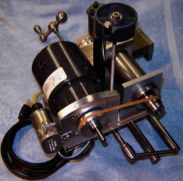 Motor mount rear view - with a rubber band in place of the belt which was on order. Scrap metal adds some "character" to the motor mount; the jacking knob was part of a broken radial arm saw and the handle holder on the pinch bolt was a randomly shaped chunk of steel that adapted easily. The pulley on the motor is slightly domed for tracking, the pulley on the spindle is flat - tracking doesn't work with the rubber band so I hope it does better with a real belt. The pulley ratio is 1.6:1 to step the speed up from 3000 to about 4800 RPM. The round ways have been left long because I'm considering adding an inch to the travel by changing the length of the base and the leadscrew so these ways will be left long until experience with the unit suggests the decision.
 Brooks' wheel center is about 3" to the left of the motor pole where my spindle center is about 2" left of the pole. The aux table will be positioned about 1" further right on the main table so the relative position of the work head vs the wheel is similar to the original but with the aux table closer to the center of the main table.
Brooks mentions removing the motor and installing it upside down plus rotating it 90 degrees when using disk wheels. This isn't possible with the motor mount I built so I may have to do some inventive maneuvering (or add another position for the motor pole) in order to use disk wheels. One possibility would be to add material at the left end of the back so another position for the motor pole could be added on that end. Not something I intend to address until I run into the issue that caused Brooks to reconfigure for disk wheels.
 The build to this point has been treated as a series of modules, where each module has been mostly completed before moving on to the next module. Integrating the modules was put off because the changes incorporated, especially the different motor mount, made it difficult to merge the modules - mainly, I needed to see the way the work head and wheel would approach each other in order to place the aux table appropriately on the main table. In addition, I omitted some of the detail items from individual modules as I proceeded so these needed to be completed too.
Integration went along normally, but slowly (as usual). Difficulty developed with the AbTec CBN wheel; when the wheel is mounted so the exterior aluminum runs true within a half thou, the CBN rim exhibits 7 thou runout. In addition, the inside of the aluminum shows 17 thou runout, the likely source of the vibration I observe. I attempted to true the CBN but this isn't easily done so I contacted AbTec, received an acknowledgment and never heard from them again.
I sharpened the teeth on one end mill and two countersinks as part of initial testing. The grinder works about as I expected other than the vibration, which is slowing things down at present. I did build and test the drill sharpening jig described below and used it to sharpen two drills but hesitate to do much more until the vibration issue is resolved.
AbTec (located in the UK) never resolved the defective wheel issue so I had little choice but to buy another wheel. I found a used Do-All CBN wheel on eBay and it works reasonably well, far less vibration and runout than the AbTec.
The traverse stop (described in Thumbprint) made setting the stop position when sharpening end mill teeth practical; the original stop setup wasn't workable in my estimation. I can now sharpen teeth of slot drills and end mills reasonably well but I haven't attempted small diameter cutters yet. The hole for the left stop was opened and tapped 1/4-20; I use a threaded rod here because it is seldom adjusted but will make another fancy traverse stop if necessary in the future.
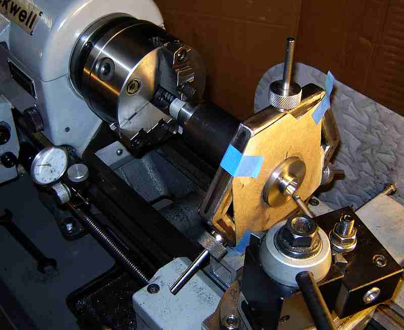
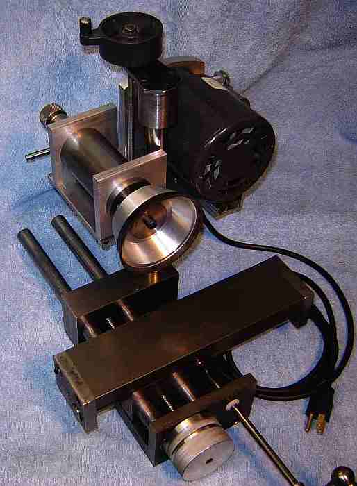
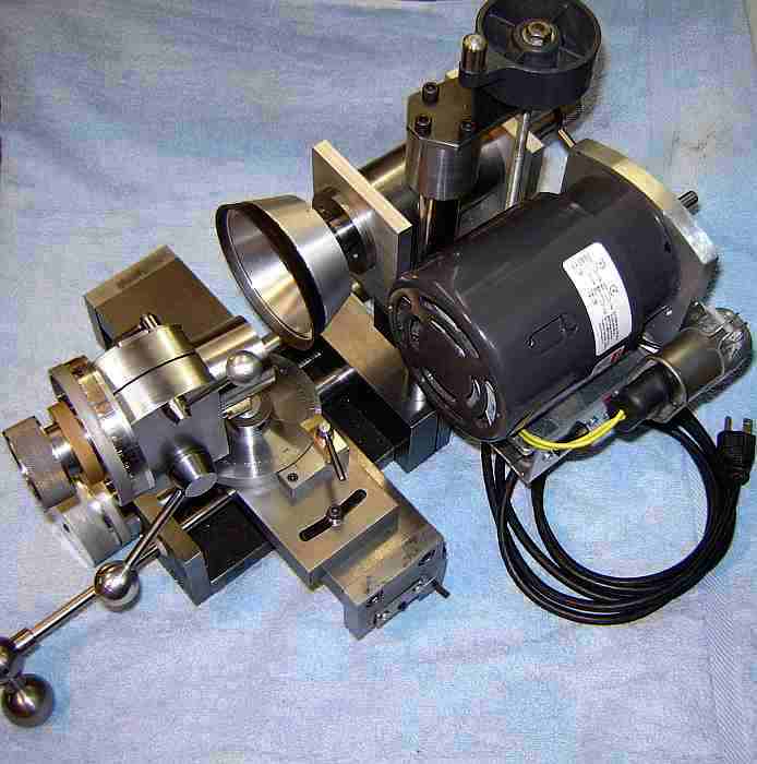
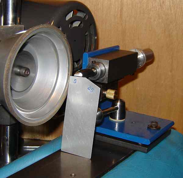
Sharpening the teeth of slot drills and end mills is handled using the Brooks work head - no additional jigs are needed for this. To set up for use, the wheel is swiveled about 5° clockwise (seen from above) and lowered so the cutter will touch only at the outer (right) edge of the wheel at wheel center height(see picture). The Aux table is set parallel to the main table. The picture shows the setup when ready to sharpen a cutter.
 Most of the work in sharpening cutter teeth is in the setup; sharpening is the easy part. My approach to sharpening the teeth of an end mill is to set the work head for the desired angles, in my case: 7 degree primary relief (tip the toolholder up) or 15 degree secondary relief, rotate the toolholder base -2 degrees (CCW viewed from above) so the teeth will be slightly lower at the cutter's outer edge.
Set a tooth exactly vertical using a machinist square for reference and lock rotation. Set the angle ring for cutter rotation to zero, then (referencing that ring) loosen the lock, rotate the cutter -90 degrees so the tooth to be sharpened is horizontal and tighten the lock. Advance feed until cutter just touches the wheel, set feed ring to zero, back feed away a couple thou. Set the traverse stop so the outer edge of the wheel stops at the center of the cutter (or slightly before).
Turn the motor on - I have it rotate CW meaning the wheel touches the edge first. Traverse so the cutter is in front of the wheel and slowly advance the feed until the cutter just touches the wheel; reset the zero feed marking to zero. Traverse the cutter to the right, away from the wheel.
Advance the feed by a half thou to one thou and traverse the cutter past the wheel to the stop and back to the right, clear of the wheel. Rotate the cutter to each tooth in turn until all have been ground. Inspect the teeth (I use a mirror to make this easier) and repeat as needed, grinding until all teeth are sharp over their full length. The traverse stop can be adjusted slightly as needed to cut all the way to the center for non-center cutting slot drills. I haven't mastered sharpening center cutting slot drills but the idea is to change the traverse stop setting to allow grinding past center on one tooth and stop short of center on the opposite tooth. This is fairly easy to do by use of the fine adjust on the traverse stop - the key being to remember to do it correctly each time you advance the feed.
When sharpening a chipped cutter it is often necessary to remove a considerable amount of material to eliminate the chip. In this situation, when the chip is just about gone, stop and reset the tooth vertical since the angle changes as the helix shortens. This isn't an issue when touching up a cutter but becomes important when sharpening damaged cutters.
If more than a couple thou are removed it may be necessary to grind the secondary relief. Judge this by the width of the primary relief land; if it seems excessive (more than 30 thou, say) then tip the work head back farther - to about 15 degrees - and proceed as above, stopping when the width of the primary land looks right. Some slot drills have a third relief ground at 25 degrees or so to provide more chip clearance - easy to do using the same method with the head tipped farther.
If the secondary relief is ground, the center of the cutter may then need gashing. The center looks wider than normal when gashing is needed and some HSMs use a Dremel to remove the excess, much like thinning the web on a drill bit. I modified my Brooks work head slightly, allowing it to tip back farther than normal to facilitate gashing.
To set up for gashing, a tooth is set vertical per the method above. The base is set +10 degrees (CW as seen from above). The work head is tipped back 32 degrees, where the lock bolt on the left side must be removed to allow this. Rotate the cutter -190 degrees (CCW as seen by the operator) so the tooth being gashed is down. Adjust the wheel height so the cutter touches at about 45 degrees above the wheel center - this allows the wheel to under cut the tooth slightly without touching the primary facet. Note that the cutter must project far enough so the wheel doesn't touch the work head. Set the traverse stop as needed, depending on whether the cutter is center cutting. Proceed as above to grind with infeed of a thou or so per pass until it looks right. Gashing is a bit of an ad hoc adventure so adjust these settings to match the angles on your favorite slot drill. This works fairly well for slot drills but needs slightly different angles for 4 flute end mills (I haven't attempted gashing 4 flute end mills yet).
Click to Enlarge
Sharpening the helix of slot drills and end mills using the standard Brooks work head isn't practical in my opinion. Graham Howe devised a separate work head for helix sharpening and kindly provided his plan. I used part of his concept but changed a number of details, as influenced by my experience with the Mini-Tinker and its plastic bearings. Graham's concept is to mount the tool being sharpened via an angle plate and then tip this plate to allow the cutter being sharpened to clear the wheel while positioning it to sharpen the next helix. Graham's approach is more stable and repeatable than the Mini-Tinker retraction method.
My tool holder is a 3/4" round drilled and then lapped to 1/2" on one end and 3/8" on the other. This is supported in plastic bearings in a block mounted on a section of 3.5" angle iron. The toolholder is free to rotate and to move longitudinally. An adjustable stop is provided to limit forward longitudinal movement.
 I used 3 balls from a large bearing as the hinge and stop to support and position the angle iron section to the mounting plate (in geometry I learned 3 points determine a plane. Finally, a chance to use that info!). The mounting plate is secured to the Brooks table by one 10-32 bolt accessed through the angle iron. A second 10-32 bolt holds the angle iron to the mounting plate with a rubber washer to limit the force applied to the balls while allowing movement so the tool being sharpened can clear the wheel as it is returned to sharpen the next sequential helix.
Below the bearing block is a smaller block to hold a 1/4" shaft with an adjustable height finger in the end that positions the helix for sharpening. The finger has a knurled nut to lock its height. The 1/4" shaft is locked in place by a split cotter with a knurled brass knob.
A short 3/8-16 stud is fixed in the mounting plate and passes through the angle to the fancy nut with the ball handle. A spring surrounding this stud forces the angle upwards against the fancy nut; turning the nut clockwise with the ball handle lowers the angle against the third ball, moving the cutter toward the wheel. The position established by the 3 balls in the chamfered holes is very repeatable. Turning the ball handle CCW moves the cutter away from the wheel so it may be positioned to the next helix without accidentally contacting the wheel. Since the angle separates from the plate only a short distance, the balls and the mounting screw remain trapped between them.
To set up for use, the wheel is swiveled about 5° clockwise and lowered so the cutter will touch only at the outer edge of the wheel at wheel center height. The mounting plate is secured so the toolholder's longitudinal movement is about parallel with the table movement although this alignment isn't critical. Secure the cutter in the toolholder with the setscrew and move the ball handle to CW (grind) position. With the toolholder moved away (left) from the bearing block about 1/4" (allows the tool to clear the finger when moved full right), the finger is angled toward the cutter so it contacts the bottom of the flute and a helix rides on the tip of the finger; the rod is locked in place using the brass knob. With the end of the cutter just past the finger, the height of the finger is adjusted to set the angle of the supported tooth to 5° below horizontal (or 25° for the relief). (To set this angle I made a small guide from sheet aluminum with 5° and 25° sections where its height matches the tool height.) Advance the Brooks traverse until the cutter is exactly even with the edge of the wheel. Use the Brooks infeed control to move the cutter away so it clears the wheel and advance the toolholder so the finger is at the other end of the helix; set the ring stop on the tool holder so it is against the bearing block and tighten the locking screw. Set motor rotation so it helps hold the helix on the finger. Move the ball handle to the CCW (retracted) position; this completes setup.
To grind a helix, with the motor off, advance the infeed until the wheel touches the cutter, back off by 3 thou and set the index mark on the dial to match the fiducial. Start the motor and, while holding light CW pressure to keep the helix against the finger, advance the tool holder until it contacts the stop collar, rotate the ball handle to the grind position, maintaining light CW pressure to keep the helix against the finger, pull the toolholder to the right until the helix clears the finger. Rotate the ball handle to the retracted position. Rotate the toolholder to put the next helix on the finger. Repeat for each helix. Advance the infeed, and repeat the above until all the flutes are sharpened.
Generally, only a couple thou need be ground to sharpen a cutter so setup is most of the work. After a cutter has been sharpened several times the land may become wider than desired. To grind the secondary relief angle, lower the finger height to set the tooth to 25° and proceed as above, grinding a half thou or a full thou at a time until the primary relief land is reduced to the desired width.
So far I've only done a couple cutters but it is interesting to see that it is possible to sharpen dull but undamaged cutters by removing a very small amount, less than 2 thou. Having read about air bearings, I was concerned that this simple approach wouldn't work properly but it works well on the cutters I've tried (1/2, 7/16, and 3/8 (an air bearing may be needed for smaller cutters, I haven't attempted anything under 3/8" yet).
 I found the cutter holder to be the most challenging part of the helix sharpener. I turned the outside of a 3/4" round to 0.730 +/- 2 tenths on the Rockwell in the 3 jaw, using the rolling center for support. The round was 8" long (including 1" for holding in the chuck, removed later). Then used fine carbide paper to polish it to 0.7297 +/- 1 tenth. I made an ER32 collet chuck and used that to hold the accurately sized round; this was set to run true within 2 tenths over its length, then drilled, bored, and reamed to size. It was turned around and repeated for the other end to make both 1/2" and 3/8" holders. Unfortunately, the 1/2" reamed hole was oversize by about two thou; in use the setscrew moved the cutter off center so the flutes didn't grind evenly. So, I made another and this was similar; I inserted a piece of aluminum foil between the cutter and the toolholder opposite the setscrew to get the flutes to grind evenly (Clearly I need reamer lessons). A friend from CTHSM loaned me barrel laps for 3/8" and 1/2" - and on the next holder they solved the size problem quickly and easily. In retrospect, an external lap would have been faster, easier, and more accurate than adjusting the OD with oil and carbide paper - but that was before I realized how well lapping works.
The bearing block isn't tricky but requires some attention to detail. The 1" HRS square bar, 3" long, was mounted in the 4 jaw chuck, trued along its length on both sides, then drilled and bored to about 0.780, size and finish isn't critical as long as the bearing thickness will be reasonable. Drilled and turned a Delrin round to make a thick tube to be a press fit in the bearing block and cut two bearings about 3/8" wide. Pressed them into the ends of the bearing block. Then put the bearing block back into the 4 jaw, carefully aligned it again and bored it to accept the toolholder with a nice sliding fit. Plastic bearings are easy to bore this way and work well dry or with oil. They do pick up grit so they mark the surface of the toolholder but both the bearings and the toolholder should last a long time in this application.
Note that this method of helix grinding depends on the bore holding the cutter being accurately parallel to the exterior of the toolholder - which is relatively easy to achieve and verify. Use doesn't require accurate alignment of the jig except to set the finger height for the desired relief. No need for the jig to be aligned with the table, etc.
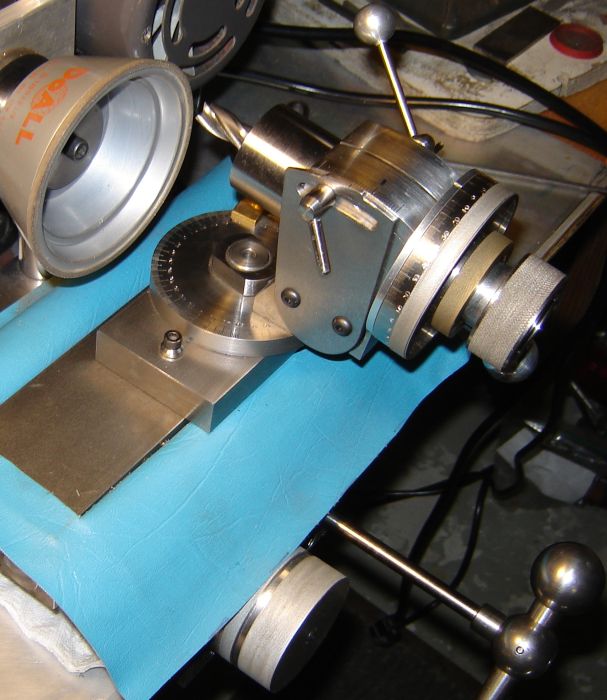
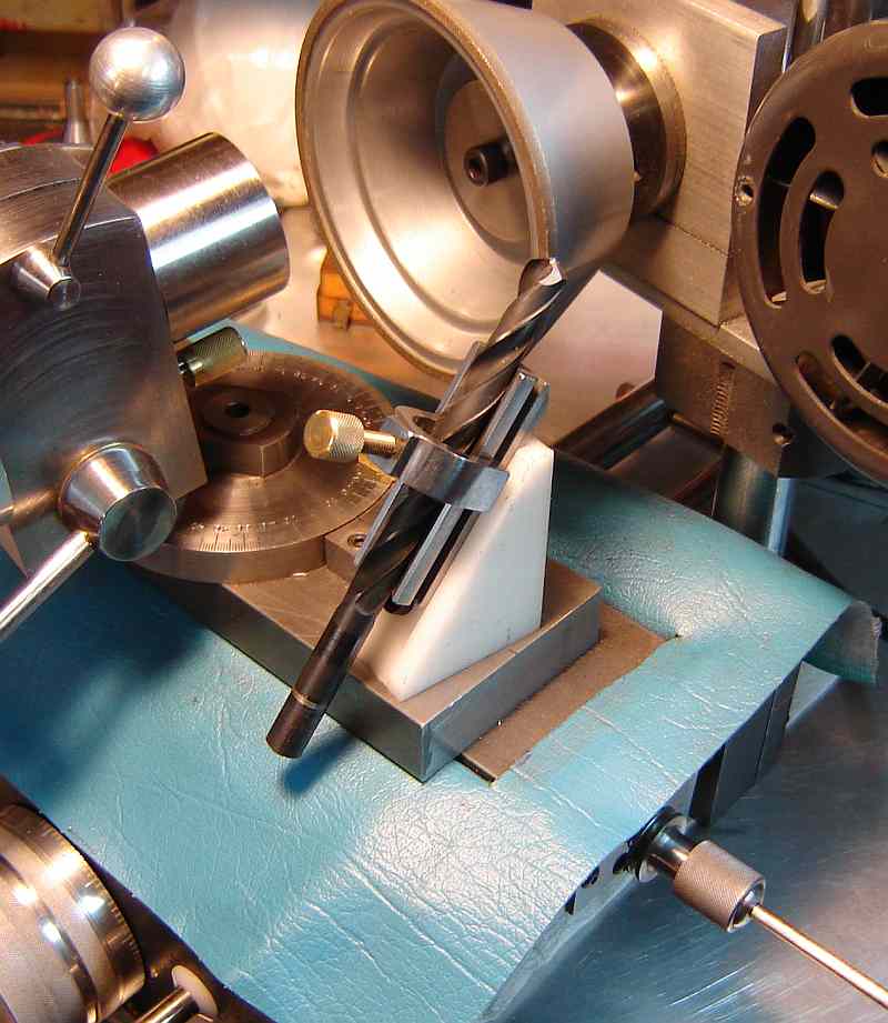
Sharpening large drills (over about 1/2") wasn't handled by any of the methods I looked at in my drill sharpening adventure. I needed to drill some large holes during construction of the Brooks so I bought an inexpensive set of Silver & Deming type drills covering the range 9/16" to 1". 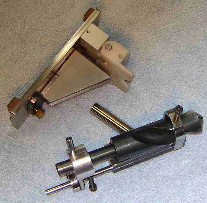 These were decent steel but poorly sharpened so I cleaned them up somewhat with the HoneDrill but this was slow and difficult on drills this large. The HoneDrill concept is easily adapted to the Brooks grinder to accomplish 4 facet sharpening; the picture shows the HoneDrill next to the jig I built for the Brooks -- the units are oriented to emphasize their similarity. The drill shown in the jig is the 1" S&D.
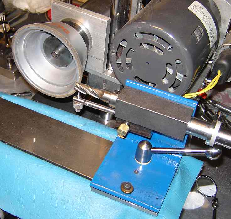
The V block is bolted to a 1/2" round, where this round mounts in my Brooks R-8 collet in place of the cutter to be sharpened. The angle between the V block and the round is 59°, duplicating the angle in the HoneDrill block. In use, the Brooks head is set to zero tilt so the round is horizontal; with the work head swiveled so the collet axis is parallel to the traverse direction, rotation of the collet about its axis sets the relief angle. The part mounted on the drill shank allows rotating the bit 180 degrees by releasing the V block clamp to position the other pin against the stop bar. The stop mounted on the stop bar sets the infeed coarse position to be identical for sharpening both lips (this stop is secured to the stop bar with a locking screw); fine infeed is via the Brooks calibrated feed control. Relief angle in degrees and infeed in thousandths are read directly from the Brooks' controls. Unlike the original HoneDrill, where symmetry of lip lengths was a judgment call, the Brooks infeed calibration makes it easy to get the point exactly on center.
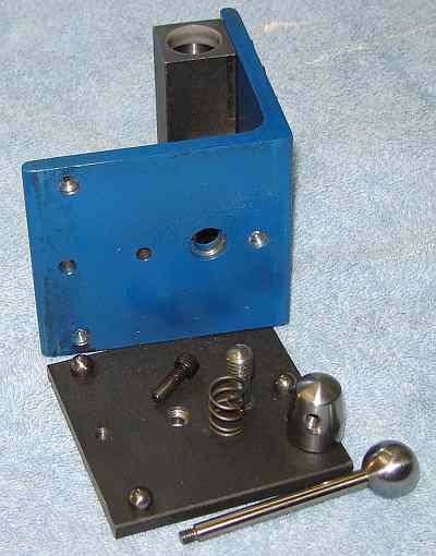
Preliminary testing indicates this simple jig works well. One wrinkle is that the part used to orient the drill by 180° conflicts with the stop bar when sharpening bits less than about 7/16". 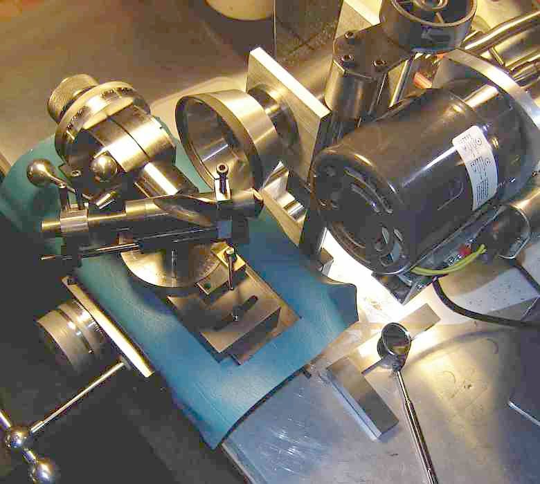 This part is actually a small V block+clamp in order to keep the two pins aligned to the drill axis properly, so it isn't possible to make it very thin radially -- meaning I'll likely end up with a separate one for smaller drills. Drills between 1/2" and 0.070 are now sharpened on the motorized 4 facet sharpener. Drills under 0.070 will continue to be sharpened by hand with the Four Facet Sharpener.
It's helpful to view the bit being sharpened periodically to estimate the remaining infeed needed; the mirror seen on the bench is used for this but I will try mounting a mirror just to the right of the wheel so this separate mirror isn't needed. A light remains to be added to improve viewing of the tool being ground. The blue shield reduces the grinding dust that finds its way to the ways and leadscrew. Several little details could be added to improve operation.
Click to enlarge
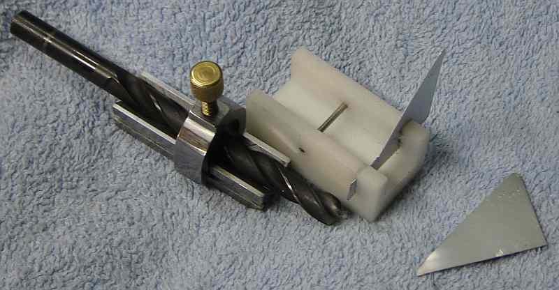
Drill point splitting is a nice feature but not possible with the above setup because the needed angles can't be achieved. The splitting setup needn't be adjustable so I made a 55° angled holder for the "V" block normally used with the HoneDrill where this is bolted to the Brooks table at an angle of 10° to provide the desired path for the edge of the wheel vs the drill bit. A screw provides a stop for the "V" block to set its position in the trough in the top of the angle block.
A guide is used to position the bit properly in the"V" block prior to placing it on the angle block. This plastic guide is just a slot into which the "V" block fits nicely. There is a cross pin which fixes how far the "V" block can slide into the guide. A 0.015" cross slot accepts a stop made from thin sheet aluminum - this sets the drill bit extension from the "V" block. In addition, the upper edge of this stop is angled to serve as an alignment guide for the drill lip, where the bit is rotated to align with this angle; the aluminum stop can be moved in its slot to facilitate this alignment. I made two of these stops, 55° and 40° since I've seen different angles used here.
To set up for splitting a point, a bit is positioned in the "V" block (using the guide described above) and locked in place with the clamp. The Brooks feed is backed off so the bit just clears the wheel. The "V" block and bit assembly is placed in the trough of the angle block with the bit to the right of the stopped wheel. The table stop is set to cause traverse to stop when the edge of the wheel is very close to the center of the bit.
In use, the traverse is set so the bit is at the center stop with the feed such that the bit is just clear of the wheel. The "V" block assembly is held securely in the slot with one hand throughout the splitting operation. The wheel is started and the feed advanced until the bit touches the wheel. Traverse the bit clear of the wheel, advance the feed a couple thou, traverse to the stop and away again; repeat until the split is a few thou from the center of the drill point - the goal is to leave a small portion of the chisel point intact. Remove the "V" block and examine the split; if the traverse has left some of the chisel point, advance the traverse stop slightly and make another pass, etc., similarly adjust the infeed if too much of the chisel remains. When one side is complete, use the guide to position the bit for grinding the opposite side. Back the infeed off and proceed as above except that now the traverse need not be adjusted, just the infeed. This isn't a particularly speedy way of point splitting but when a one or a few split point bits are needed this will do it.
The corner of the wheel shown could be sharper to make a better corner on the split but still it works reasonably well. 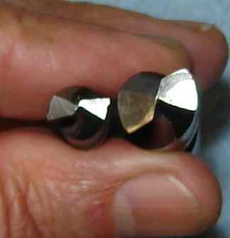 Most of the split point bits I looked at while figuring out how to do this have thicker webs than normal and splitting the point seems to be a convenient way of thinning the web, allowing a bit to be stronger than regular bits due to the thick web. The larger bit shown at right was purchased as a split point bit so it has the thick web while the smaller bit was split on the Brooks - note that the thick web causes a much larger vertical section at the split.
Click to enlarge
Sharpening slitting saws requires a simple fixture to hold the saw and index the teeth. The inverted "U" shaped piece of stainless came from the metal pile at Newtown's dump. It supports the blade at a convenient height above the table for wheel clearance and is held solidly to the table with one bolt through its foot. A 1/2" hole at top center holds a piece with a 1" diameter shoulder 1/16" thick; this accurately positions the 1" center hole of the saw blade. A clamp made from a large washer and a camlock, similar to that used for the 7x tailstock, with a nut and spacer below secures the blade in place for grinding.
The tooth index holder is a copy of a Starrett clamp used with their indicators; it locks both rods simultaneously when the knurled nut is tightened. The index is a small piece of stainless sheet, silver brazed into a 0.015 slit in the end of the rod. To set the index position, a line scribed at 6° through the center of the saw position is used to line up a ruler and this is used to set the index position. With the saw blade held CCW against the index and then locked, 6° relief will be ground on each tooth. This fixture grinds only the top of a tooth; there is no provision for re-gulleting. This fixture handles up to 6" diameter slitting saws with about 5 teeth per inch of circumference. Blades with fine teeth need a different scheme (so I avoid them).
To setup for use, the tooth index is adjusted to 6° (or whatever relief you prefer)for the blade diameter and number of teeth and the table stop is set to grind the indexed tooth without touching the adjacent tooth. The camlock clamp is adjusted to accommodate the blade thickness using the bottom knurled nut. With a tooth against the index and the blade clamped, the Brooks infeed is set so the tooth is almost touching the wheel (with wheel center matching blade height).
To sharpen a saw the infeed is advanced until the indexed tooth just touches the wheel and the infeed index mark is set to match the fiducial line, then advance the infeed about a thou. Traverse the tooth past the wheel and move it away enough so a tooth (or the index) doesn't touch the wheel as you index, unlock the saw, advance one tooth and lock the blade with the new tooth CCW against the index; repeat for each tooth (it is helpful to mark one tooth with ink to keep track of where you are). If more must be ground off to complete sharpening, advance the infeed and go around again.
There is a sort of rhythm to it which makes it fairly quick to go around and only a couple passes are needed to sharpen a saw unless it has been damaged. The 2.5" blade shown was slightly damaged by running too fast in steel and took under 5 minutes.
I found this fixture interesting to make because it uses the camlock and the Starrett clamp, both of which I had made previously, soon after I began machining. Judging by the way these came out I've gotten some useful experience over the last 5 years :-)
As a typical HSM, I leave my thumbprint on my work by making changes to the plans. Naturally my changes are "improvements" on the original :-)
One clever thing about Brooks' design is that, unlike the Quorn, it is made from off-the-shelf materials - no expensive castings. The changes I made have mainly been aimed at making recovery easier should I mangle some part of the construction. In particular, the "frame" consisting of the base and the center slide, ways and table all must go together and if one must be replaced I expect it would be difficult without starting over - probably possible to bore the ways holes out, bush and rebore but it would be a considerable effort. My changes attempt to make it easier to recover from a machining error (or subsequent wear and tear) without requiring starting from scratch.
My leadscrew uses a shielded ball bearing rather than a plain bearing and includes pre-load. The leadscrew diameter was changed to 3/8". The hole for the leadscrew has been opened to 1/2" and a 10 tpi Delrin nut press fit to accommodate the leadscrew. My thought is that tapping 10 tpi in steel and getting the fit desired for a lead screw would be beyond my skill level (and probably strength). A plastic nut is easy to single point and easy/cheap to do over if it doesn't come out well -- that is, I have a "Plan B" for this.
Traverse uses a cog belt from a line printer driven by a gear on the end of the traverse shaft. Thin cable was tried rather than Brooks' chain method to drive the table but didn't work - not enough friction. Plan B (the cog belt) seems to work well (so far). My tension mechanism is simpler to build than the original.
The round ways will be retained mechanically rather than with Loctite. Plan B is to replace the mild steel ways with case hardened ways, Enco Part# 505-3298 but these are much more expensive, about $1/inch.
Brooks' traverse handle may be awkward to use (depending on the angle it is at) to traverse the surface being sharpened so I substituted a lathe type handle.
Rather than making collets I purchased an R8 collet set and bored the tilting head slightly larger to accommodate the larger toolholder needed for these collets; the toolholder is 1.1" diameter, up from the original 1" diameter.
 I changed the traverse stop, Part 32, from a long threaded rod to a short threaded part containing a collet which locks a plain 4mm (0.154")x10" rod. The tip of the collet is visible poking out of the holder.
In use, the collet is loosened (using the two knurled parts), the rod pushed through to set the coarse stop position, and the collet tightened to lock the rod in place. The left end of the collet holder threads into the hole in the table end plate; the 20 tpi thread yields 50 thou per turn fine adjustment; the spring avoids slack in the thread affecting the setting. Simple, quick to adjust, works well.
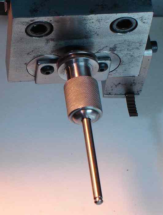 Here it is installed in the right end of the table. Brooks included a micrometer scale reading in thousandths - I didn't include this because I adjust the stop position by eye rather than by measurement. A scale could be added if needed. The rounded end on the collet nut was done with a graver as decor - a little whimsical machining.
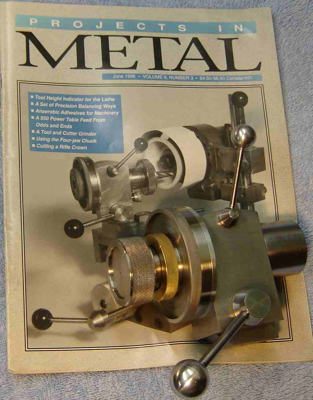
Brooks' original article appeared in "Model Engineers Workshop" April/May and June/July of '93 and then in "Projects in Metal" in June '96 (I have this PIM issue, courtesy of Richard Hagenbuch). These articles seem to be essentially identical with minor oversights in the plans duplicated in both articles. The little items I've noted appear below in random order. In addition, I noted some things described in the article or drawings differ from the pictures.
Part 6, the table top shows the holes to secure the auxiliary table on the side away from the operator but the pictures show the aux table on the operator side of the table top. The pictures show the table without the T slot described in the drawing; it is unclear whether the additional holes for the aux table are needed if the T slot is incorporated...
The sketch of the chain assembly shows the sprocket conflicting with the ways.
The length of the rod for the traversing spindle is not given (easy to determine).
Part 9, the swivel base bolt, is shown as 15/16" but should be 1+9/16". It has a 1/4" reamed hole but the purpose of this hole is not given... In hindsight, this hole is probably to hold a setup aid for ball end mills; I didn't think of this early on and it is unclear whether I can re-work my collet holder so the tool being sharpened can be positioned far enough back to allow using the swivel this way.
Part 10, the swivelling base is missing a dimension for the perpendicular piece - the dimension arrow is there but no size; looks like 1.875 or so. Also, the dimension for the swiveling base is given as 2.25" but should be 3.25". Note: The right side of the perpendicular piece must be on the center line of the rotating base - this to allow sharpening ball end mills.
Part 13, the tilting head is missing the height of the hole for the toolholder; this seems to be 2". The section removed to fit the perpendicular of part#10 must be on the tool holder center line, again for sharpening ball end mills.
Part 19, the raising block, shows a hole for the finger support used when sharpening the helix on an end mill; this hole is not shown in the pictures so I suspect the helix procedure given is theoretical.
Part 32, endstop, is for use on both ends of the table. On the left end the stop seems to fit in the lower hole (the upper hole is in the drawing but the "on end only" should probably read "one end only") while on the right end it fits in the upper hole, apparently to avoid conflict with the traversing rod; this detail isn't explained so this is my assumption. Having tried this endstop setup, I found it inconvenient to use because relatively large movements are needed occasionally, made awkward by the long threaded section - it needs a rapid coarse adjustment - so I changed it as described above.
Part 34, tilting head side plate, is shown tapered in the drawing but is square in the pictures (doesn't affect function). The height of the bolt holes isn't given but seems to be 1/2". The center hole isn't needed, may have been used in making the arc'ed slot. The side plate should be tilted forward slightly to allow the head to tip down a bit; this is shown in the pictures but is not in the drawings. From the pictures, Brooks drilled the mounting holes in the swiveling base to provide the tilt but I drilled these holes before making the side plate so I accommodated this tilt via the mounting holes in the side plate. I rounded the bottom of the side plate to match the part it bolts to (because I think it looks nicer :-).
Based on my description of building the Brooks grinder I hear from other HSM's who would like to build one. I try to answer questions that arise and aren't covered by Brooks' article or my description and generally stay in touch with other Brooks builders, some of whom keep me abreast of their progress.
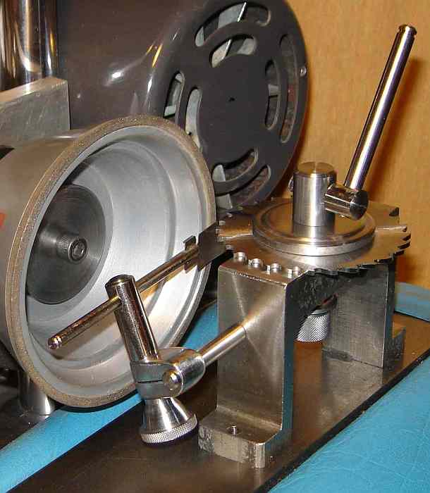
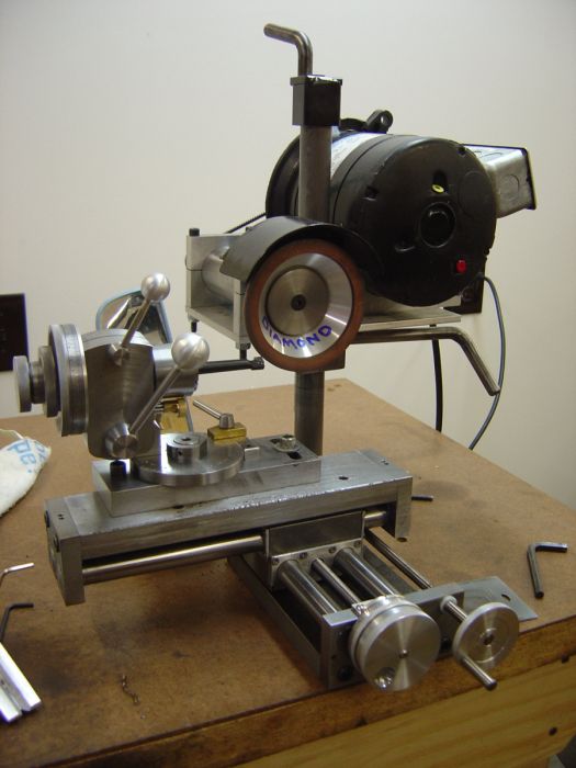 Larry Rudd completed his Brooks in November 2010 and is proceeding to add jigs and tooling for the various sharpening tasks which arise in his shop. Larry sent a picture of his machine set up to sharpen carbide boring bars using a diamond wheel.
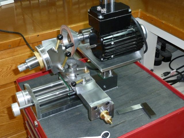 Jim Schroeder completed his Brooks in December 2010. Jim sent a picture of his machine set up to sharpen carbide end mill teeth using a diamond wheel. He added an extension behind the rear base plate to support the motor so his wheel is slightly farther aft than mine.
This page was last modified by John Moran, HTML tweaker. If you have a comment on this site or its contents,
click here scroll down and click again.