* GadgetBuilder.com *
Last Modified:
Click to Enlarge
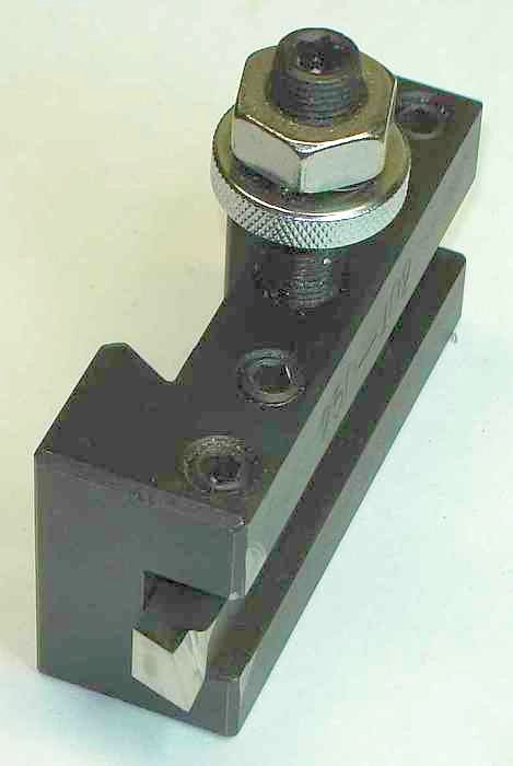
The "vertical shear bit" is an adaptation of a finishing bit used on shapers as described by Moltrecht in "Machine Shop Practice" Vol. 2, ppg 13-15. The idea is to use a cutting edge nearly parallel to the direction of motion so it slices across the work at a narrow angle, a shearing/slicing type cut. It is limited in depth of cut to three thou or so but provides an excellent finish on many difficult materials, e.g. HRS round which can be cantankerous at times. Works well for very small infeeds, into the tenths. For such a simple to grind tool, the results are remarkable.
Grinding is simple because there are only two surfaces. Grind the rebate shown so it goes from top to bottom of the bit along the side at about 15° as shown in the picture. The angle is necessary but can be most anything from 10° to 40° from vertical as long as it is in the correct direction so the bit will cut when advanced from right to left. Larger angles allow faster feed and may not dull as quickly; Moltrecht suggests 25°. After grinding the rebate on the wheel circumference I grind it flat along the top to bottom line by touching the rebate to the side of the wheel - this makes it easier to hone later.
Grind an end relief angle to meet the rebate, 10° has worked well for me but again, it's not critical as long as it is greater than 5°. 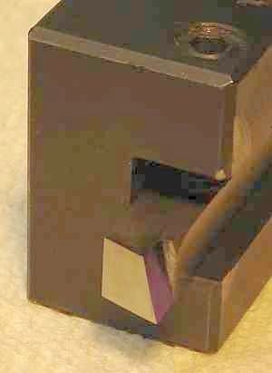 If you expect to use the bit for facing then you can grind a gentle curve from top to bottom; if ground straight it will work for normal turning but not for facing. The gentle curve will work for turning and/or facing. When facing, the contact point must be below center. I've tried a rounded version for facing but results weren't as dramatic so I use the flat shear tool shown here and face with the tangential. In this picture the rebate is inked to improve contrast.
Hone or stone the edge to a fine finish, preferably polished, on both surfaces. This is easily done by hand if both surfaces are flat.
This lathe bit is unusual in that center height isn't critical - whatever section of the nearly vertical cutting edge contacts the work will slice a thin chip. As one might expect, it works best with fine auto-feed. The swarf is wispy - long, thin, and twisted, unlike any other bit I've used. If the edge dulls just change the height to use a different part of the edge or re-hone when the whole edge is dull. Since the chip slides along in contact with the bit for a fair distance (due to the narrow angle) this promotes heat transfer and wear. It is helpful to run at modest RPM with fine feed plus use cutting lube to minimize wear on the bit.
The same slicing type edge can be adapted for finishing with a boring bar (or a fly cutter) where it will again remove only small amounts of material per pass. The shear bit was discussed on chaski and one of the machinists, BryceGTX, explored it in depth - well worth looking at his pictures and thoughts on the shear bit concept.
Some history: I found info on this tool in a file on the 7x12 group (where I moderate) when it was posted there by Bob Bickerton in December 2005. Bob found it in an article in the July/August 1997 HSM, "Grinding Tool Bits for a Smooth Cut" by Frank Burns who called it a "contrary finishing tool". Frank used the concept from a description of a shaper tool he found in "Advanced Machine Work" from 1925, reproduced by Lindsay Publications. (A similar shaper tool is found in "Machine Shop Practice Vol. 2" by Karl Moltrecht (1981) -- works well on my shaper).
Parting can be a problem on the minilathe; I found improving the fit of the gibs and slide plates helped as did positioning the compound so the tool bit is over the cross slide rather than cantilevered out toward the headstock.
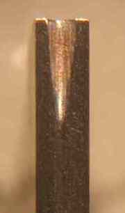
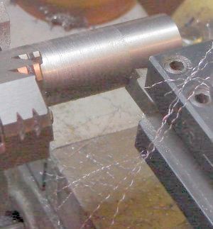
A surprising improvement in parting occurred when I added a groove to the tip of the tool as suggested in Geo. Thomas' book, "Model Engineer's Workshop Manual". I couldn't easily set up the Brooks to grind the slight "V" in the top of the tool as shown in the book so I used the Dremel with a small carbide disk to try his suggestion. My groove is deeper than he illustrates but it works very well. Once the groove is added, the tool can be sharpened and re sharpened by grinding the front of the blade with a 5° to 7° relief angle; the wire edge in the groove should be removed with a piece of fine carbide paper folded and passed along the groove. The picture above shows my (1/16" wide cobalt T style) parting blade with the added groove. Cobalt earns its keep in parting blades - I've seen this blade's tip turn straw color while parting stainless.
I suspect the steep angle on the sides of the top groove give it a slicing action, similar to the vertical shear tool, for much of the tool width; this seems to make cutting easier.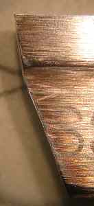 The top groove also causes the chip to be narrower than the slot and to be "crinkled" so it is fragile; it exits the narrow slot more easily than the chip from a blade with a flat top. In use, a blade with this top groove has a small raised section in the middle of the slot during parting.
In sharpening parting blades it is easy to over-heat the edge because it is narrow. A simple way around this is to realize that the 7° relief angle need not be carried all the way down the blade. The support provided by this small angle is needed just under the cutting edge but a steeper clearance angle can quickly be ground below the relief area without worry about overheating - it won't affect the cutting edge. This makes it quick and easy to sharpen the cutting edge without over-heating because little material need be removed - the picture shows the side profile on my blade.
Still, I don't push my luck when parting on the 7x12 (or the Rockwell). Work up to about an inch in diameter parts nicely on the lathe. In parting work larger than this, blade extension and the resulting flexibility becomes an issue. When circumstances allow, I make a shallow groove and finish with the bandsaw. More thoughts on parting technique.
In "Design and Use of Cutting Tools" Leo St. Clair had some interesting observations on HSS and how to select among the various grades. The basic M1/T1 grade of HSS (without cobalt) is the strongest and toughest material but begins to lose hardness above 750F and should not be used above 1000F. Adding 8% cobalt improves hardness at cutting point temperatures to 1100F but reduces strength and toughness. Adding more cobalt (12%) extends the temperature range to about 1150F but further reduces strength and hardness. The cast alloys (T15, Tantung, Motung, Rex76, Rex95, etc.) handle 1200F or more but are somewhat brittle and their cold hardness is less than some regular HSS. Carbide handles even higher temperatures than cast alloys but is more brittle. So, there is a broad spectrum of cutting tool material where the tradeoff is mostly between hardness at temperature vs strength/toughness and where cost generally rises with temperature capability.
I have been purchasing cobalt HSS with the idea that more expensive is better. St. Clair recommends using plain HSS unless the application can take advantage of the red heat hardness of the more exotic alloys. I suspect I mostly turn at modest temperature so I'll try regular HSS to see how it holds up in my shop. On interrupted cuts, regular HSS should generally perform better than the alloys because it is tougher and can stand impact better - so HSS and slow speed is the ticket here.
I have read varying suggestions on how to grind HSS tools, some suggest grinding at temperatures where the bit turns straw color is Ok while others suggest dunking periodically in water. St. Clair indicates that it depends on the type of HSS. Hardness of HSS depends on the carbide crystals embedded in the HSS; raising the temperature into the 1000F+ range allows these embedded crystals to dissolve in the iron, reducing hardness. Cobalt keeps the crystalline structure intact until a higher temperature is reached, extending the red hardness range. The cast alloys are different - they're cast because they can't be heat treated: the hardness remains the same after the alloy cools from exposure to high heat, unlike regular HSS where the crystalline structure is destroyed by exposure to high heat. His recommendation is to not grind regular or cobalt HSS at high temperatures and also to not cool any bits by dunking them in water since this can cause stresses which lead to later failure.
Carbide is very heat tolerant and extremely hard but brittle compared to HSS. Carbide is very strong in compression but not so strong in shear. Negative rake causes the cutting edge to be more in compression while positive rake causes the edge to be more in shear. There is always a bit of both shear and compression so the rake angle just shifts things to favor one or the other. Relief should always be minimal to keep shear forces small.
A major failure mechanism in carbide is edge breakdown where a micro chip occurs in the edge which increases local force and heat - causing that defect to eventually grow into an edge failure. A sharp edge on a carbide tool is more prone to initiate this type of breakdown so this edge is sometimes honed off slightly; counter-intuitively, this prolongs tool life by reducing the micro chipping tendency which starts edge breakdown. Sharpening carbide on a green wheel can cause micro-cracks in the material near the edge (leading to similar edge failure) so green wheels should not be used within 1/16" of the edge; fine diamond produces a smoother and longer lasting edge.
Carbide is very hard and very tolerant of heat. To take advantage of this and minimize chipping the edge, negative rake tooling is favored along with relatively high speed and feed. The edge is used mainly to begin the cut - if speed and feed are sufficient then the shear point is such that the chip flows over the top edge without touching and makes contact some distance back from the edge. Most chip breakers have a flat area preceding them where the chip should not touch the flat but should contact in the depressed area forming the chip breaker. The idea is that heat is generated in the chip from bending and with slow speed/feed heat would be transferred from the chip to the tool close to the edge where it can't dissipate well since there is tool material only on one side. Using carbide at low speed/feed typically results in "cratering", a little hole on the flat just back from the edge caused by the hot chip; as the crater enlarges it weakens the edge and eventually causes edge failure. When speed and feed are high enough the chip contacts back from the edge where heat dissipation is sufficient to avoid cratering since carbide can tolerate high heat as long as it can dissipate rapidly by conduction.
Few small lathes (like the 7x12) have the power needed for the speed and feed required to take advantage of carbide. Positive rake carbide needs less power but is prone to edge chipping and negative rake tooling needs high power to avoid cratering. In addition, small lathes are often limber and prone to chatter; chatter imposes a rapidly varying chip load and the load at the high point is often enough to chip the edge of carbide tools instantly.
This page was last modified
. If you have a comment on this site or its contents,
click here.