
* GadgetBuilder.com *
Last Modified:
The Phase II QCTP comes with several toolholders but more would be better, allowing more bits and the clamp knurler to be instantly available. The only problem is the price of the AXA holders, typically upwards of $15 on eBay, more from a regular supplier. It is possible to make toolholders with a mill, given a dovetail cutter. However, dovetail cutters are expensive too. The frugalmachinist had the answer for both the dovetail cutter and the toolholders.
The cutter was turned from a 1.2" round with a 1/2" shank to fit the mill's cutter holder. All turning was done without removing the work from the chuck to ensure concentricity. A small shoulder was left on the shank to allow resetting the depth of the cutter in the holder in case it was removed to change inserts. The slope was turned to match the 60 degree angle and size of a TPEG 322 carbide insert: the bottom is 1.10 diameter. A very small dot was put in the center of the bottom for reference using a center drill in the tailstock. A split sleeve was made to fit the QCTP's boring bar holder to accept the 1/2" shank; the dovetail cutter-to-be was inserted and tightened into the boring bar holder. A scribing block was used to mark a horizontal (diameter) line through the center dot previously made on the bottom of the cutter.
The boring bar holder was then mounted in the mill vise and a machinist protractor was used to orient the vise so the seat could be milled for the carbide insert. The mounting area was milled down until the face of the insert was exactly in line with the previously scribed diameter line (half of which was, of course, milled off in the process). The inner edge of the TPEG 322 is exactly at the dot made earlier. The back of the TPEG insert is smaller than the front and the back should extend beyond the 60 degree section which supports it by a few thousandths on the bottom and side -- the tool can be re-installed in the lathe and adjusted (after the flat is cut and the insert mounted) to achieve this if necessary. The insert is installed with super glue and the center of the mounting hole spotted, the insert popped off and the hole drilled. I drilled the hole completely through, tapped it 6-32, cut the button head screw slightly long, installed the insert and then simply filed off the protruding threads. The cutter was removed from the boring bar holder and a flat was milled on the shank.
Home made cutters don't come with instructions for use so it took some experimenting to decide how to make dovetails once I built the tool. The bulk of the material is removed with normal milling techniques to leave a large slot. Then, the dovetail cutter is used to cut the sloped section of the dovetail. With the cutter stopped I lowered it to touch the bottom of the large slot, then raised the cutter 5 thousandths. I started with 400rpm and cut about 1/3 of the dovetail's depth on the first pass. Subsequent passes removed 20 thousandths until full depth was achieved. This dovetail cutter is a type of flycutter and makes the same noise as it operates so I arrived at the above settings based on the sound of the cutter.
I tried various other approaches with poor results (YMMV). Attempting to cut the complete dovetail depth in one pass seemed to go fine (slightly slower feed required) but part way through the tool was pulled down and began to mill the center area in addition to the dovetail; thinking something wasn't tight enough I tried this a second time with the same result -- your tool might work better...
From the carbide insert's perspective, this dovetail flycutter provides one long interrupted cut. I didn't expect the insert to last long in this application but it survives reasonably well at 400rpm -- I was able to complete 2 toolholders before I had to rotate the insert. Running the cutter at 1000rpm caused the insert to chip rapidly, failing to complete one pass. There is not a lot of clearance between the sloped section of the cutter and the work so chips get in between and gall/polish this area on the cutter. When the cutter chipped it caused rapid galling of the sloped area because the insert wasn't removing the material so it rubbed the cutter -- it pays to watch for this to avoid damaging the tool irreparably should an insert fail. Operating at 200rpm might increase insert life considerably at some loss in feed rate.
The dovetail cutter can also be used as a facemill of sorts. When facing, the cutter has a wide contact area so it is wise to take shallow cuts to avoid chatter; I took 5 mils out of the large slot on one tool holder as an experiment and it worked nicely. Avoid facing while cutting the dovetail, this would make it hard to tell if the cutter moved downward, as happened when I tried to cut a full dovetail in one pass.
The 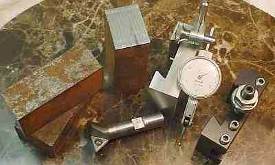 raw material for my toolholders was 3 pieces of steel from a local machine shop which was kind enough to cut it to length and throw in a chunk of scrap aluminum. I used the aluminum to test the dovetail cutter and make a DTI holder that fits the QCTP. The AXA type toolholders are 3x1.5x1. The length and thickness of the raw material required adjustment, done with the big face mill included with the milling machine. The ends were squared and all were within a couple of thousandths in size, simplifying measurements and clamping during following operations. I don't have a roughing cutter so I used a 1/8" slitting saw to remove the bulk of the material from the slots for the tool and dovetail. This was slow but left a nice finish in the tool slot for the tool to sit on; I made one slot with an endmill but the finish wasn't as good.
Cutting dovetails was interesting because the width is more critical than I expected. I had read about HSM's making a precise dovetail test gauge to verify the size but didn't appreciate what they were dealing with until I tried it. I came up with a crude scheme which works for making a small number of dovetails. I placed a Phase II toolholder in the mill's vise and positioned the (stopped) dovetail cutter so it touched one side of the dovetail, then set the mill's horizontal stop for this point and similarly for the other side of the dovetail. The dovetails were then cut using the stops to get close to the correct size; the width was a few thousandths under because of the method used to set the stops. Then, the dovetail was tried on the toolpost and widened 3 thousandths at a time until it fit. (File the corners as needed if they interfere with the fit; I found that looking along the length of the dovetail with a light at the opposite side helped to detect any interference.) The mill's vise is precise, allowing this trial-fit technique to work nicely; of course, the holder being machined was re-installed in the vise with the same orientation each time. An obvious alternative (which wasn't so obvious at the time) is to remove the toolpost from the lathe and use it to test the holders without removing them from the vise...
Matching metric setscrews were used to hold the tool bits in place, allowing one hex key to work for both purchased and home brew toolholders. The long metric setscrews for setting height weren't available locally so for now (and perhaps always) I'm using 10-32 bolts. I don't have a way of bluing the holders so they will stay as machined.
The DTI holder is higher than the toolholders and has a fixed pin to set the height above the tool post because this needn't be adjusted in use. The clamp was copied from a nifty Starrett design and works better than the clamp on the inexpensive magnetic holder I purchased -- as usual, I copy only the very best :-)
Click to Enlarge
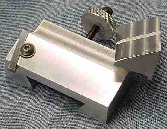
A tangential toolholder was on my list of things to try for a while but I procrastinated because I didn't want to lose the convenience of my QCTP: the ease of adjusting tool height plus the ability to instantly change tools is very hard to give up. The picture shows my attempt to have my cake and eat it too ;-)
There seem to be two common designs for tangential tool holders, the Freeby and the Burke. As best I can tell from the pictures, the Freeby is side-tangential while the Burke is corner-tangential. The Freeby design has been used and documented by Ralph Patterson and Richard Hagenbuch(passed away Dec 2014), both of whom provided information and advice during construction of my version of the Freeby design. Both Ralph and Richard used aluminum for their tool holders so I did likewise, mainly because it is so much easier to work than steel.
The concept of Freeby Berger's design is to tip the bit forward and left by 12 degrees and slope the top of the bit opposite to these tilts at 30 degrees in a diagonal direction (the interaction of these angles is hard to visualize without the tool to look at). The result is the side (or the front) of the bit cuts with relief provided by the mounting angle of the tool and rake provided by the angle ground into the end of the tool. Unlike regular tools used in the QCTP, the Freeby tangential setup can do both turning and facing without moving the position of the toolholder to another face of the QCTP. Of course there are some limitations to this tangential arrangement: cutoff isn't handled, boring isn't handled, threading requires some contortions and a special tool, left to right cutting requires adding a bit to the other end of the toolholder and perhaps some rotation of the QCTP (depending on the task). The QCTP provides the missing capabilities nicely using conventional toolholders.
A 3x1.5x1 chunk of aluminum was the raw material. After the dovetail was cut, the outer side was milled at a 12 degree angle such that the bottom one inch is angled. A 3/16" slot was milled into the angled section of the side at an angle of 12 degrees to the front -- the picture will help in understanding what needs to be done. The centermost edge of the slot intersects the top of the angled side 1 inch up from the bottom - another view. A hole was D/T 10-32 for the button head locking screw. Experience showed that it was difficult to see the bit in use so the area above the bit was milled away to improve visibility (this could be done more elegantly with a tilting vise). John Gedde built an AXA holder from my description and shared his drawing pdf. Interesting build method here.
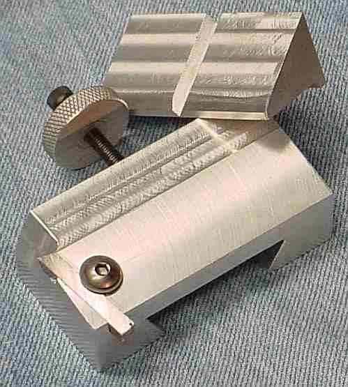
A major convenience with the Freeby design is the ease of constructing and using a sharpening fixture. I used a scrap of aluminum, angling it at 30 degrees and then adding a V to the 30 degree face. The bottom was milled to leave a shoulder along the rear edge; this slides along the grinder's guide to allow moving the bit across the wheel - the dimensions are specific to the grinder so adjust as needed.
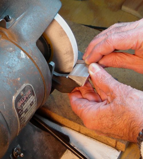 In use, the bit is placed in the V, the fixture is placed on the grinder's guide and the bit is held down with finger pressure; the fixture is slid back and forth to use the whole width of the wheel. The bit will have the end slightly hollow ground at a 30 degree angle. Because the wheel passes across the bit toward the cutting edge a hooked (wire) edge will result; after grinding, hone the sides on a sheet of fine carborundum paper over a flat surface to remove these hooked edges. It takes a few minutes for the initial grinding but re-sharpening is very quick using the fixture. The aluminum fixture seems to absorb heat well, especially if a drop of water is placed in the V before grinding. To reduce the rake angle and thus produce a bit for use on brass, pack the front of the guide up slightly.
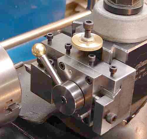
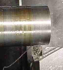 The tangential is different than normal QCTP toolholders because the bit is so close to the toolholder, making it harder to see from some angles. The big surprise was the finish achieved on steel; it was clearly smoother than I was able to achieve with my other tools. Further, chips formed long curls when taking fine cuts (something I couldn't do on my steel test bar with regular tools), the curl goes to the left of the bit rather than to the right. I suspect that the difference in results is because the tool is sharper than my best grinding efforts on regular bits plus the rake angle is steeper than most of my tools. The picture shows the normal clearance angle and the chip curling to the left; for improved finish, rotate the toolpost slightly CCW to reduce this angle. The washer was removed and the top of the button head was faced to provide clearance when facing large items.
After polishing a turned steel cylinder I noted a thread-like pattern with 32/64/128 tpi (varied along the length) faintly visible. I tracked this to slight binding in the gears; I reduced the meshing depth and lightly filed a couple of teeth on one of the 20 tooth metal gears to solve the problem. I find that for most turning and facing I reach for this tool first so it is definitely a keeper.
One detail on the bit: I cut it in half because the protruding end was a problem both in use and when storing the holder while using another on the QCTP.
Some observations based on a couple year's experience with the tangential toolholder. The tangential cuts normally moving toward the headstock and can take very deep cuts (I sometimes cut 100 thou in steel) where the feed rate must be reduced to accommodate deep cuts. Surface finish is generally poorer than normal when taking deep cuts. Avoid deep interrupted cuts - the tool will be driven lower in the slot by the hammering; a piece of paper, cut to width and placed in the bottom of the slot improves the grip a bit (pun intended). The tangential provides a much improved finish when cutting while moving away from the headstock however the cut should be minimal, say 2 or 3 thou. I use this tool whenever possible (in preference to other tools) so it has been sharpened repeatedly - about 1/3 of the bit is now gone.
Update: In replacing the original bit I found its replacement didn't face properly because it wasn't square. I checked a number of bits and many weren't square so this is a generic problem. A square bit is necessary with my design to make the angles come out right so I'll order a Mo-Max since they seem to be ground square.
 Update 2: Apparently I got lucky with the parallelogram shaped tool bit (noted above) which worked well for years - but hid a design problem. Because the 12° rotations are done sequentially when machining the holder, the tool angle is off such that the bit needs to be rotated about its axis (looking down) CCW by about 2 degrees. I haven't figured out a simple way to machine this in my shop... so I use a narrow paper shim under the bit to get the angles symmetrical for turning and facing. If you look through this thread a different way of producing the tangential holder is described which may make getting the angles right easier. Info on calculating the compound angle in posts 4/5 of this forum thread.
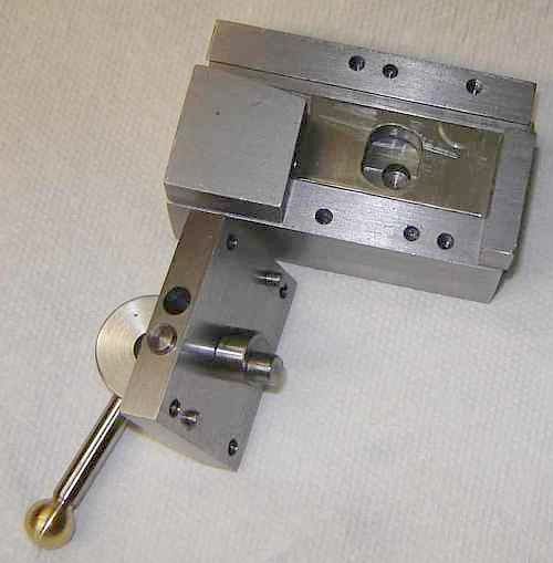
I got tired of changing the height setting when moving the tangential between my two lathes so I built a second tangential tool but made it to fit a regular toolholder. It doesn't work as well as the dovetail version, probably because the extra distance from toolpost to tool tip (see picture) makes it less rigid. In addition, the bit sticks out farther than regular bits in QCTP toolholders so when swapping back and forth I have to wind the CS in and out. I much prefer the original design so eventually I shimmed the Rockwell QCTP up to match the 7x12 so all my holders now work on either lathe without tweaking height.
Click to Enlarge
I built the George Thomas "Retracting Toolholder for Screwcutting" partly as an exercise in dovetail cutting on my new (to me) shaper. This toolholder retracts the cutter (by flipping a lever) so the carriage can be wound back without changing the cross slide position; makes threading faster and easier as well as less error prone (when combined with an auto-stop or especially with a dog clutch). 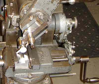 Plans are in "Model Engineer" November 1981 and in Thomas' book, "Model Engineer's Workshop Manual". Material cost was modest, about $7 for the square steel (plus minor pieces made from scrap) but it took a while to build, partly because I was learning to run the shaper and had to grind the dovetail cutter. (The retracting tool holder is also available as a kit.) Interestingly, the jig for grinding threading bits was used to grind the dovetail cutter simply by setting the angles with a protractor. I made a video of the retracting toolholder and the dog clutch.
(A much different retracting tool holder is used with the round QCTP.)
Plans are in "Model Engineer" November 1981 and in Thomas' book, "Model Engineer's Workshop Manual". Material cost was modest, about $7 for the square steel (plus minor pieces made from scrap) but it took a while to build, partly because I was learning to run the shaper and had to grind the dovetail cutter. (The retracting tool holder is also available as a kit.) Interestingly, the jig for grinding threading bits was used to grind the dovetail cutter simply by setting the angles with a protractor. I made a video of the retracting toolholder and the dog clutch.
(A much different retracting tool holder is used with the round QCTP.)
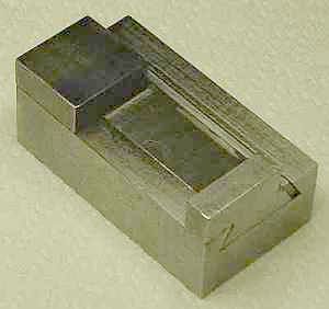
Since this was meant as a learning exercise on the shaper, I started by squaring and sizing the stock with the shaper. The Thomas plans provide the order to make the cuts in the major pieces; this is a great feature because it makes it easy to avoid getting to the point that it is difficult to hold the work, something that would be easy given the shape of these parts. I took one picture part way through construction when I finished the first dovetail and had fitted the gib.
 I used the mill to finish the center opening in the slide after removing the majority of the material with the shaper -- to avoid grinding left and right hand knife tools for the shaper... Some things, like the gib, were particularly easy on the shaper and would have been more difficult to set up on the mill. View of interior.
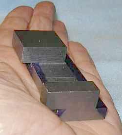 I found the slide's shape difficult to visualize because of the lumps and bumps that appear as the initial cuts are made. As shown here I marked the dovetails in ink to ensure they're put in the right place.
The design was revised to replace the tongue Thomas used to mount the toolholder with a dovetail to fit my QCTP -- another chance to practice dovetail cutting! Fortunately, I learned enough on the first dovetail to get a better finish on this one - I avoided letting the cutter get into the narrow corner which causes a LOT of chatter. The vise on my shaper takes some fussing to get the work aligned parallel vertically and horizontally simultaneously, mostly paper shims and/or tapping with a hammer as the vise is tightened. I couldn't get the work positioned so I could use both left and right hand cutters without moving the work in the vise so I ended up reversing the work so I could use the one cutter but this meant precisely positioning the work so the dovetails would align properly - several minutes with a DTI, hammer and shims each time but the dovetail came out great.
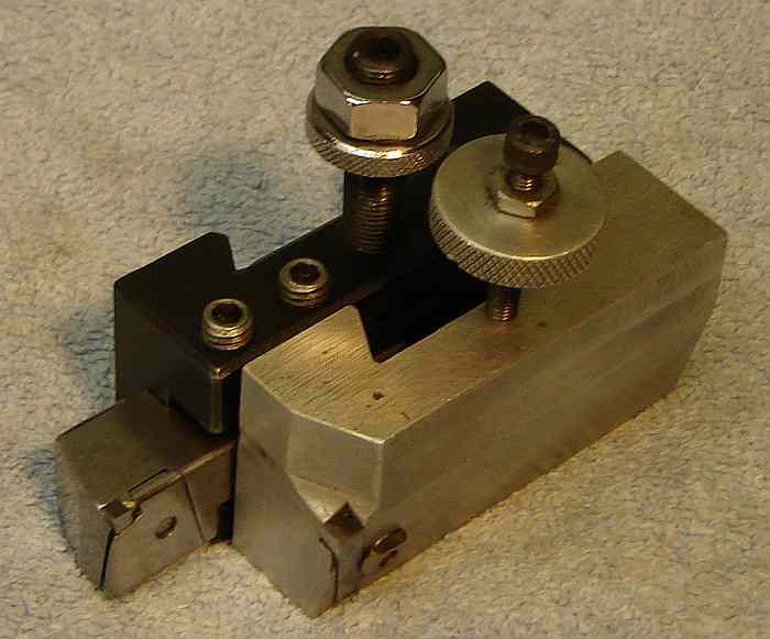
Here is the holder with the tool retracted. I used 6-32 screws for the gib adjustments and to hold the bridge piece in place, 10-32 screws to hold the cutter and for the over-center adjustment. 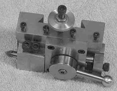 The bridge also has two pins to precisely position it but their main function is to make it easy to install the bridge piece against the force of the retracting spring. The screw on the right allows adjusting the over-center force that locks the cutter in the forward position. The gib is short and lapped to a good fit so the gib screws are touchy, only a few degrees between smooth operation and locked. I didn't use lock nuts, just a bit of dental floss in the threads for friction (to simplify adjustment). Overall, a very well thought out design and excellent build instructions.
One unusual feature is that the toolholder uses 1/4" round bits. This allows rotating the cutter slightly to accommodate the helix angle, as required for coarse threads. The bits are mounted at a 7 degree upward angle so they have a small back rake, unusual for a threading tool. This required adding a hole to Cleeve's grinding jig with a 7 degree angle, of course. I assumed the cutter's angle would need to change from 60 to 55 degrees or so but it seems to be closer to 58 degrees than 55... I'm still fiddling with this. The rake seems to make the cut smoother but that could be wishful thinking to justify the work in making the toolholder.
Click to Enlarge
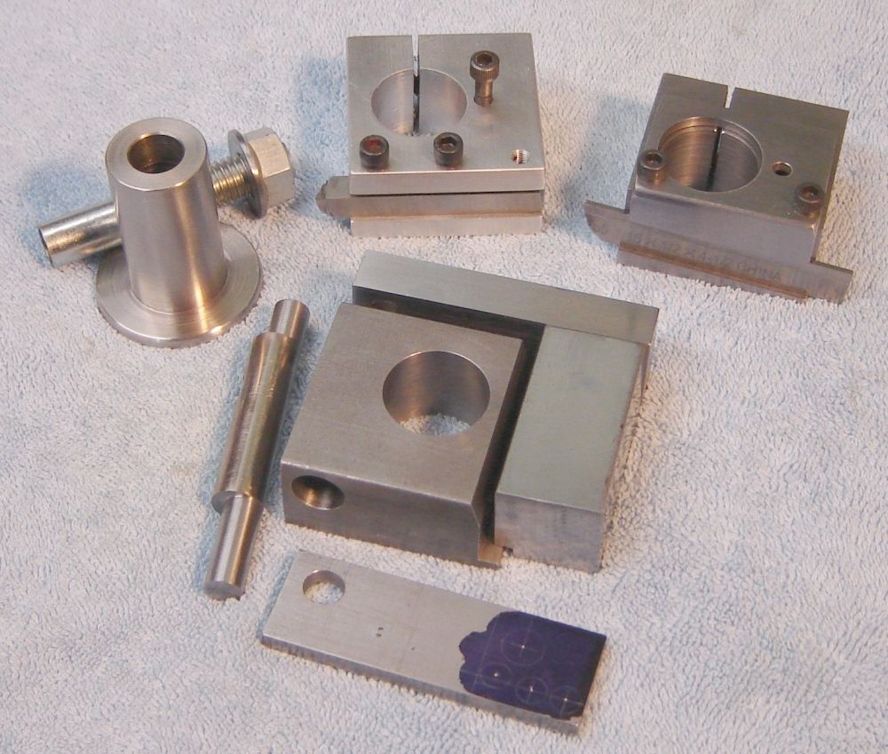
The AXA QCTP is larger than needed on the 7x12. The distance from the center of the AXA tool post to the tool tip is farther than desirable, providing leverage that can incite chatter. While smaller dovetail QCTP's are now available, a round QCTP is easy to make, easily sized for the minilathe, and accommodates a retracting tool holder which I've wanted to try. The picture above shows a standard tool holder and a parting tool holder with back rake similar to the AXA parting tool holder. My retracting tool holder (a variation on Cleeve's design) is shown under construction, where the major pieces are partly complete. Note: my compound base is LMS #1777, used to lower the compound by 1/4" (or, modify the original base, directions in 7x12 Group Files see Compound_Mod_JWE.pdf). Also, extended cross slide travel on my machine is used to advantage for the flip over threading tool holder.
The parting tool holder has about 5 degrees of back rake built in which requires the tool to be held low on the holder, note that the support for the tail end of the tool is fairly thin - this limits how low the tool can be held. As the tool is extended from the holder the tip height increases. When the holder is lowered as far as possible the tool tip rising above the center line limits the allowable tool extension and parting diameter. If this becomes an issue then the wide base on the tool post would need to be thinned or the rake reduced. So far, this holder works very well.
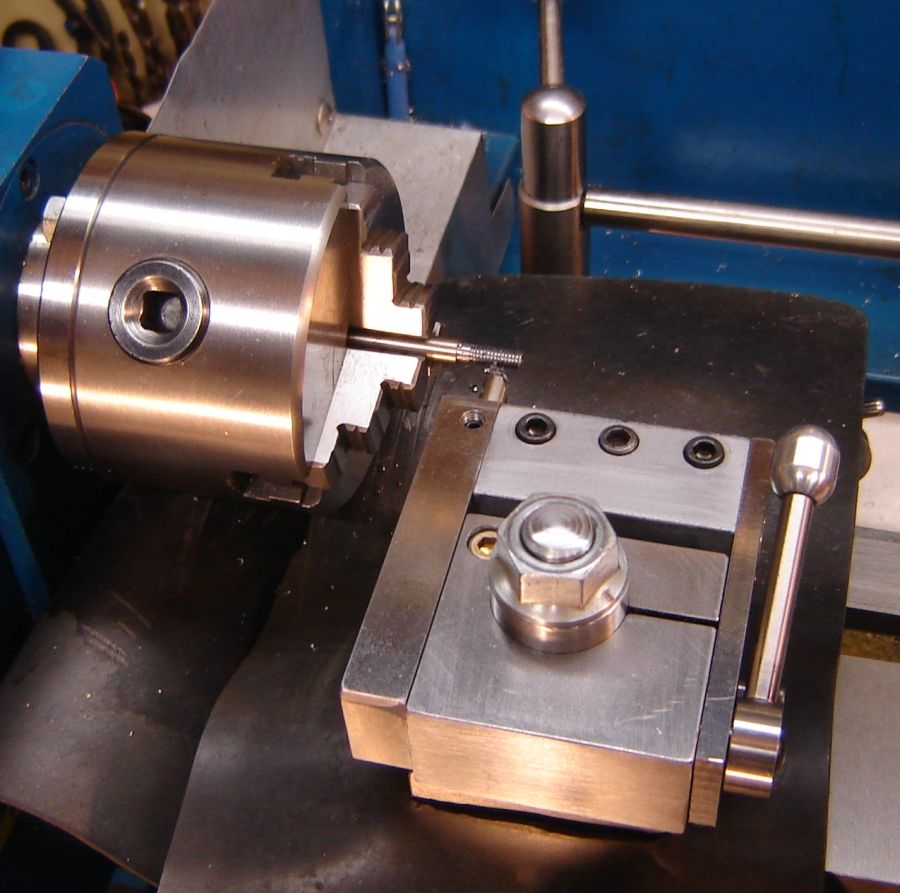
This 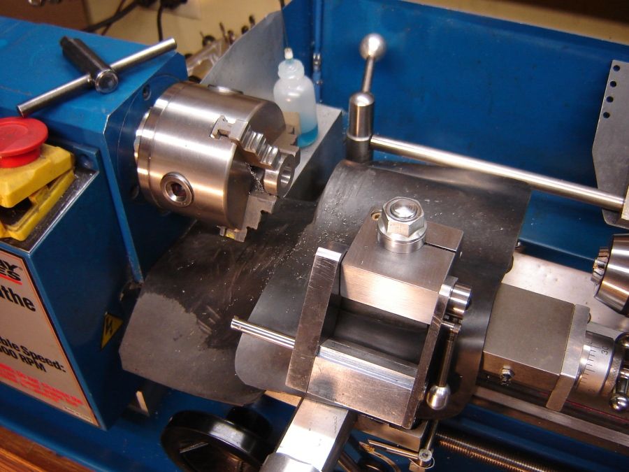 retracting tool holder is a combination boring bar holder and threading tool holder which includes retraction as well as flip up to allow easily inspecting the bore being worked on. In the picture at right it is shown flipped over for access to the bore. Retraction is controlled with the lever on the right side which rotates the cam. I was concerned about chatter since the arm isn't locked down but it hasn't been an issue in preliminary testing. It is convenient to be able to retract the tool for regular boring, no scraping during withdrawal. Unlike the other holders, the bolt to clamp it to the TP is accessed from the far side of the holder, this to avoid conflict with the retract cam.
Most of my boring bars have a 3/8" shank so this holder takes that size. It uses a reamed 3/8" hole slit on one side plus three 10-32 screws to clamp the bar solidly in place - light torque on any of the 3 screws locks the bar so with all 3 it is very secure. The AXA holds 5/8" bars so I used a split sleeve to hold my 3/8" bars and the split cotter in the AXA may not have been quite as solid because of this sleeve. Should I need to use my 5/8" bar I'll make a regular boring bar holder (non-retractiing) which is considerably simpler - only one part plus bolts.
External threading requires removal of the boring bar, then a 1/4" round threading bit is installed in the left arm of the retract mechanism. The picture shows it cutting the first test thread; the control lever is against the forward stop to move the bit full forward. This retract mechanism holds the bit fairly far forward which limits the diameter that may be threaded to about 2.75" - I've never threaded anything near that size so it won't affect my use. An operating peculiarity I didn't forsee is that the tool tip moves forward as the lever is moved forward but as it nears position its motion is upward due to the cam. Works fine but looked odd when I first noticed it. The tip of the boring tool is closer to the support for the retract so the upward move is small, so small I hadn't paid attention to it. A difference from the Thomas design is that it is easy to flip the tool out of the way to test size with a nut or to use the tailstock die holder to tidy up. It allows retraction for internal and external threads (the Thomas shown above is for external threading only) where the same round threading bit from the Thomas holder is used for external threads(I'll eventually make a shorter one for this unit).
To complete this tool holder family a tangential will be needed along with more holders for normal bits. If it works well then a knurling tool can also be added.
The round TP and its holders are much smaller and lower than the AXA setup. The 7x12 is quite small and this smaller toolpost makes the lathe feel bigger because access is more open - I've gotten used to the AXA over the last 9 years and this gives it a much different feel, almost like a new lathe.
This page was last modified
by John Moran, XHTML tweaker. If you have a comment on this site or its contents,
click here.