
* GadgetBuilder.com *
Last Modified:
Click to Enlarge
I read "Design and Use of Cutting Tools" by Leo St. Clair and was impressed by his clear description of cutting angles and what they do in single point cutting tools. St. Clair worked in industry optimizing design and use of lathe bits during the transition from HSS to carbide so he covers both areas well. The basic concepts for both materials are the same, where the cutting bit material's strength and toughness change the design details required for best performance.
This foray into tool grinding theory was educational but the resulting bits cut too well, so well they chattered in the 7x12 and the Rockwell 10". Chatter was a problem on both machines during deep cuts with high feed rate until I limited the feed rate by reducing the side relief (see below) and reduced the width of the cutting section. I expect these tool designs work particularly well on large, rigid machines in good condition (smaller side relief on my limber machines helps me avoid the chatter regime). The synopsis below of St. Clair's material provides some useful insight on how and why cutting angles are chosen.
Update: As time goes on I find I'm using the St. Clair grind more and more, mainly because I understand it better and adjusting the angles to 4 degrees for side relief and 10+ degrees side rake has made the tools work well on my limber lathes. While the tangential remains my most used tool, the St. Clair tools are the next most used lathe tools in my shop, especially for roughing. Ease of resharpening using a jig is a major factor for both the tangential and St. Clair tools - makes them work predictably, much like an insert.
In the home shop "best" tool performance is hard to quantify because we generally don't repeat an operation long enough to wear a tool out, whereas tool life was a major concern for St. Clair. Tool life, in the form of infrequent sharpening, is important but ease of resharpening and initially grinding the tool are also important. What I gleaned from the book is that most tool parameters need not be optimum to work reasonably well although some angles may need to be selected appropriately depending on the material, e.g. brass may self feed and hog in or chatter if the tool angles for steel are used - as is well known in home shops....
After reading this book (twice) I made a very simple grinding jig to produce bits with angles appropriate for cutting steel. This jig is easy to build and makes it quick and easy for beginners and experts to grind bits per St. Clair's design. These are bits for quickly removing material as well as bits for improving the finish after roughing. This jig is useful for common external roughing and finishing bits, not form tools or boring bars. The bits produced should be oriented exactly perpendicular to the work so a QCTP that accomplishes this is helpful; a QCTP clamping to a cylinder will require careful adjustment for each tool change so cylindrical QCTPs need extra attention. The key to easy resharpening is making it easy to reproduce the angles initially ground into the bit, exactly what the jig accomplishes. The jig described produces bits which cut while moving to the left but it is straightforward to build a similar jig for bits which cut going the other way. Surprisingly little grinding is required for bits produced with this jig so it doesn't take long to make them initially and even less time to resharpen -- I ground a bit from a blank in under 3 minutes. This simple jig allows new users to grind bits that work well without spending a lot of time understanding the various angles. I've found I'm using these bits more, especially for roughing, as time goes on.
The following is a brief synopsis of terminology and concepts from the book to help understand the reasoning behind St. Clair's tool design. If you'd like more info on the why's and wherefore's, the book is an excellent source and very readable (but difficult to find and expensive to buy). Video explaining similar terminology.
The relief angle is the angle below each cutting edge; without a relief angle the tool would simply rub on the work rather than cut. The optimum relief angle for most materials is 6° to 8°; this provides good support for the cutting edge to prevent it crumbling from the force exerted by the chip. In soft materials a larger relief angle can be used to allow faster cutting.
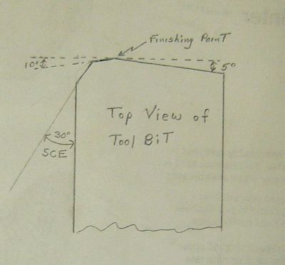
A common lathe bit approaches the work from the right so the left edge must be relieved as well as the front of the bit. This is called the Side Cutting Edge (SCE). The SCE may be perpendicular to the work (leftmost tool in picture) or angled to the right; this is called the SCE angle.
SCE joins the end cutting edge (sometimes via a radius) and then the tool end angles away from the work. This is called the end cutting edge angle. There is also relief below the tool end, needed to avoid rubbing on the work(6° to 8°, as usual). The final point on the end of the tool which touches the work (just before the end cutting edge angle) is called the "finishing point" because the finish left on the work depends on this point.
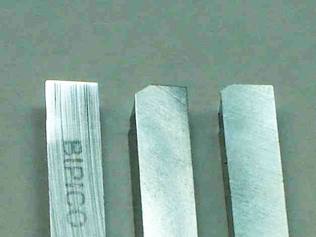 Cutting forces on the tool are large so to minimize wear and damage to the cutting edges they need as much support as possible from the surrounding tool material, especially the finishing point. The 85° angle on the leftmost bit shown is relatively weaker than a more obtuse angle which would provide more nearby support. A radius on this sharp corner would be stronger and would wear less. However, radius corners are more prone to produce chatter. Therefore, St. Clair suggests a SCE of 30° to 45°; the other bits shown have a SCE of 30°.
There are actually multiple SCE's on these two tools: the relief angle extends beyond the 30° angled section so if the depth of cut gets beyond this it can still cut without rubbing. The chip thickness equals the feed rate on the perpendicular section but is thinner on the 30° section; this thinner chip exerts less force on the cutting edge so it wears it more slowly. To further protect the important finishing point, a smaller angle can be used just prior to the finishing point to further thin the chip, providing even more protection for the finishing point. In the third tool shown a narrow section with a SCE of 10° is used. In addition to reducing wear on the finishing point this shallow angle improves the resulting finish. This is effectively a dual tool with a roughing section followed by a finishing section. The 10° section must be kept narrow or it may cause chatter. I've seen 3 separate chips, each going in a different direction, from this type of tool - looks peculiar but works fine.
To further improve finish, this narrow section just preceding the finishing point can be ground at 0° to produce a finishing tool. The width of this section should be 1.5 to 2 times the feed rate. Again, if too wide it can induce chatter.
Cutting forces are always perpendicular to the cutting edge so the first tool shown has all the force along the axis of the work. By angling the SCE some force is perpendicular to the work axis so it takes up any slack in the cross feed - this is often an important aid to minimizing chatter in machines that have a bit of backlash ... but an effect that is seldom considered in tool design.
The top of the tools shown above have been left flat: no side rake or back rake. While it is commonly thought that back rake reduces power required, St. Clair cites tests showing this not to be the case. Mainly, he uses back rake for chip control.
Side rake does reduce power required plus it can be used to control chip direction - the chip effectively flows down hill. Typical side rake is 10° to 15°. The chip naturally flows perpendicular to the cutting edge so some side rake may be helpful to counter this in controlling chip direction.
Back rake is generally used in combination with side rake to control the direction and type of chip produced. Often, it is used to produce a chip breaker by angling the chip down so when it comes to the resulting rise it doubles back on itself causing the chip to break. If the chip coils and moves along the depression then side rake can be added to slow its progress so it does coil into itself and break. On brass, negative back rake may be used to avoid self-feeding. When a tool with back rake is resharpened the cutting point becomes lower so after several resharpening cycles it is so low it must be ground away and you start over; this uses HSS up faster and requires more grinding time so back rake is used only when required.
 An alternative chip breaker is to simply grind the top front of the bit to leave a narrow (10x to 15x chip thickness) horizontal shelf along the front of the tool with a rise of about 1/16" behind the cutting edge. The chip, which normally flows perpendicularly from the cutting edge, runs into this rise which either bends it enough to break it or causes it to coil onto itself and break. Adjust side rake of the shelf if necessary. The picture at right shows a chip breaker, where the finishing point shows a little wear.
Tool height should be set to put the finishing point on center. When side rake is used the leading edge of the tool won't be on center; because of the small edge angles on the bit it takes some effort to see and adjust the height properly. Improper height will cause poorer tool performance so take the time to get this right.

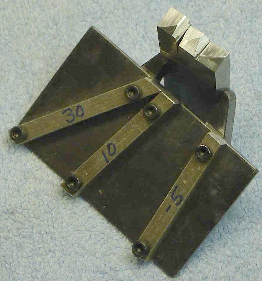
The grinding jig is trivial to build: mine is a rectangular 2"x3" piece of 1/16" steel with three 1/4" square pieces of aluminum screwed to it, as seen in the picture above. The aluminum pieces are set at the angles written on them in the picture: 30, 10, and -5 degrees. The screws are cut off and sanded flush on the bottom. This jig isn't from the book -- it's my simplistic interpretation to implement the book's suggestions easily. (A larger jig to accommodate the tool holder would allow re-sharpening without removing the tool from the holder - hindsight is always 20/20.) Bits produced with this jig all look similar (i.e. a roughing bit looks a lot like a finishing bit) so it may be helpful to mark the bits (or their tool holder) to indicate their intended use.
The grinder must provide a guide to keep the jig oriented so its long side is parallel to the wheel axis, as shown in the first picture where the miter is used for alignment. An alternative for grinders that don't have a miter is shown below.
The relief angle of 8° below the cutting edges is set by angling the grinder table so when the bit is on the grinding jig the top edge of the bit touches at the 8° tangent point. 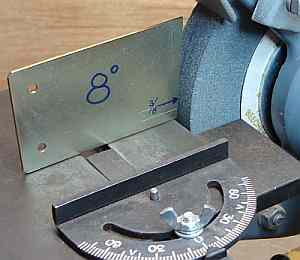 To set the table, make the simple guide suggested by Frank Dorion and shown in the picture. This is a thin metal bevel with an 8° angle as shown having a line scribed even with the top of the bit when the bit is on the grinding jig. The table is adjusted so the end of this scribed line is touching the wheel - put a light behind the guide to make the tangent point easily visible.
To grind a new bit, it is oriented so the angle on its end has the longest part uppermost (to minimize material removal). The picture at the beginning of this section shows the result after grinding when bits are oriented as described. Other orientations will work, you just have to grind more HSS away. It is important that a small relief angle be used so the cutting edge is well supported but this need only extend 3/32" or so below the cutting edge; a steeper clearance angle is helpful below this. The steep clearance angle means little HSS need be removed when sharpening the cutting edge -- this minimizes heating of the cutting edge while grinding which can reduce hardness. The steeper clearance angle can be ground quickly with little concern for heating because it is fairly far from the cutting edge so it won't affect the HSS characteristics.
I grind the SCE along the left side first by pressing the front 1/4" of the bit against the wheel with the long direction of the bit parallel to the grinder axis (bit extends to the left of wheel), checking frequently to get the ground area to just reach the upper surface at the same time for the full 1/4". Little material is removed so this doesn't take long. Based on experiment I found that less than 8° relief here, perhaps 4° to 5°, helps reduce chatter on deep cuts although a more rigid lathe may handle the larger relief without chatter. The smaller SCE relief limits the feed rate by rubbing so don't use auto-feed with this approach.
Next, use the -5° guide to position the bit with respect to the wheel and grind the end relief angle onto the front of the bit for the necessary distance depending on the type of cutter desired - for the rectangular cutter this would be full width but for the others slightly less need be ground. It is easy to come back to any of the jig angles if more needs to be removed since the jig ensures alignment. If this is a rectangular cutter you're done (unless chip control is desired).
To make a roughing bit, use the 30° guide to grind the SCE for the desired length, which depends on the expected depth of cut (the SCE along the side of the tool will handle deeper cuts if you accidentally go beyond the 30° SCE depth. Based on my later experiments less than 8 degree relief on the side of the tool should reduce or eliminate chatter; try it and adjust as needed for your lathe if chatter occurs on deep cuts.
To make a roughing+finish cutter, ensure the ground areas for 30° and -5° meet and extend down the face of the bit at least half way. Use the 10° guide on the jig and just touch the bit to the wheel. The goal is to make a very narrow section between the other two angles, typically less than 1/32", narrower for slower feeds or less rigid machines. If this section is too wide the tool will chatter in some applications. This land is visible on the leftmost bit in this picture.
To make a finishing cutter proceed as for a roughing+finish cutter but rather than using the 10° guide, use the miter (or the edge of the jig) to accurately grind a small land at 0°; very little material is removed so just touch the bit to the wheel and check to see how you did. 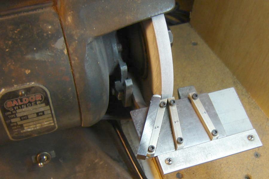 Again, this should be very narrow to avoid chatter. The finishing cutter should be used to take small cuts of only a couple thou, mainly it is used to produce a nicely finished surface. Even without chip control on many materials this bit produces tiny short chips rather than long strings.
The jig can also be used to hone the edge of the individual facets of the tool by placing the bit against one of the angle guides with the jig held at about 7° from vertical, then pulling it across some fine carbide paper on a surface plate. A block could be milled to 7° to improve honing accuracy if you're ambitious. As a slacker, I don't hone the front of these tools, just the top.
To add side rake, I orient the bit to the right of the wheel with the left side of the tool uppermost and grind the tool top until the wheel meets the edge - less than 1/4" of top width need be ground. Then, this area is held against the side of the wheel to flatten it by grinding only the right side of the tool. This will leave the top flat and at about 10 degrees. This flat area is easy to hone to a polished finish on carbide paper. A polished finish makes it more diffult for material to stick to the top (forming a built up edge) especially if cutting lubricant is used while turning.
The picture at right shows my ancient Baldor grinder, modified by bolting a plate to its cast iron rest and then adding a strip on that plate to guide the St. Clair jig - so it is possible to easily adapt grinders that don't have a miter to work with this jig.
I tested these bits without adding chip control angles to get a feel for how they work. Note that bits with a 30° SCE angle cannot cut to a shoulder - I found the rectangular tool tends to leave a slightly rough surface so I use the tangential to clean up the inside corner. Nor do I use the second tool with only two angles (30 and -5); I found the tool with the 10° angle added works very well for roughing and leaves a better finish. The finishing tool with the 0° center angle works well although I prefer the vertical shear tool for most finishing. So, I use two of the 4 variations on St. Clair's theme that I tried, the one with the narrow 10° section before the finishing point and the finishing tool with a 0° section. I learned a lot from reading the book; I expect these tools work best on rigid machines in good condition and my lathes don't measure up so I must use caution to avoid chatter on deep cuts.
Cutting force is proportional to the length of cutting edge engaged by the work (and depth of cut) - as with form tools, chatter is more common when this length increases. I found limiting the width of the 30° section to about 1/16" helpful in reducing chatter plus the 10° section width is always kept small, about 10-30 thou. Reduced relief on the 90° SCE then seems to control chatter - I reduced this angle by stoning so don't know the exact angle (seems about 4°) where this limits the feed by rubbing at high attempted feed rates which eliminated chatter for me. I expect the required relief varies with the length of the 30° SCE section and the limberness of the lathe so it may take a little experimenting in each case. (Side rake changes relief too so this can affect what works best.)
Wear is slow in most materials because the finishing point is better protected than in most tool designs. Resharpening is very quick unless the tool has been damaged. A tool which is only dull can be restored quickly using the jig, needing only a light touch on each facet. As usual, be cautious when grinding the small facet near the finishing point so it doesn't become too wide. Recovery if this facet becomes too wide is easily handled with the jig but wastes a little HSS.
The angles on either side of the finishing point are small (nil for a finishing bit) so it is difficult to judge correct grind by eye. Even with a square held against the bit it's hard to see. Watching the tool work makes it obvious whether it is correctly ground since the chip produced and direction it flows allows evaluation of operation.
Wear is judged by looking at the size of the wear land extending down the front of the tool; this wear land is usually largest at the finishing point. Surface finish degrades as the width of the wear land expands. A little experience with these tools allows judging when the bit needs sharpening based on the width of this wear land.
Cutting lube is especially important on deep cuts which use the steep section of the SCE - the top of the tool in this area gains a built up edge quickly unless a good lube is used.
This tool design also works well in carbide. I've had excellent results resharpening brazed carbide boring bars with a 10° facet preceeding the finishing point.
First I built the tangential tool partly because it had a sharpening jig that allowed it to be sharpened quickly and easily.
Then I made Cleeve's sharpening jig because it took me so long to grind threading bits without a jig.
Now the jig for St. Clair style bits allows sharpening this type of bit accurately and easily.
The vertical shear tool doesn't use a jig for sharpening - but it is so simple to grind that it doesn't need one.
So, I definitely see a pattern developing here, especially considering the drill sharpening jigs which are only a variation on the sharpening jig theme....
This page was last modified
by John Moran, HTML tweaker. If you have a comment on this site or its contents,
click here.