* GadgetBuilder.com * © 2008 John Moran
Last Modified:
Sharpening bits freehand for thread cutting on the lathe is always time consuming because of the frequent checks needed to get the angles correct. I recently purchased "Screwcutting in the Lathe" by Martin Cleeve which describes a simple jig for sharpening threading bits. There are only three parts plus some pins and fasteners so construction effort is modest. As with most gadgets I build, the concept is the critical part - considerable freedom on dimensions shouldn't affect operation. Time to sharpen or resharpen a threading bit using the jig is much reduced and the result is much more professional looking (no facets as when I freehand). Sharpening is completed on the side of the grinding wheel or disk sander so the ground surfaces are flat.
After sharpening my threading bit and seeing the nice job it did, I realized that the problem with freehand sharpening is the difficulty obtaining the same angle when presenting the tool to the grinding wheel after examining the results and deciding it needs "a little more taken off". This jig makes it easy to repeat the angles so the result cuts well and is very professional looking i.e. not "faceted". This jig can also be used to sharpen bits other than threading bits.
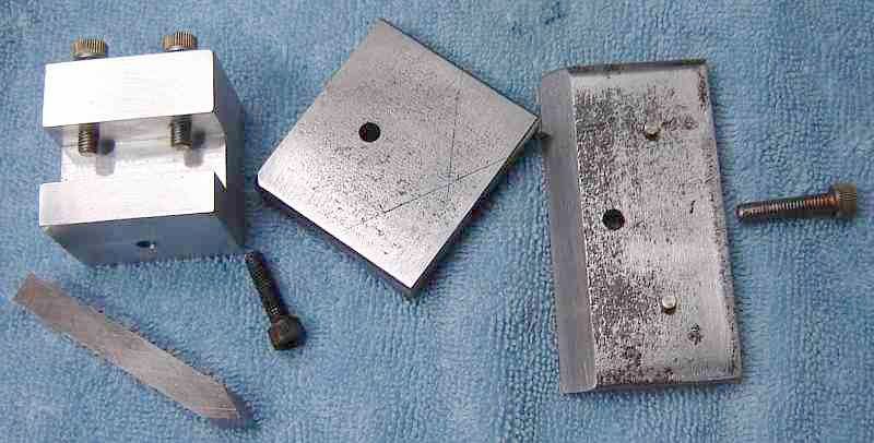
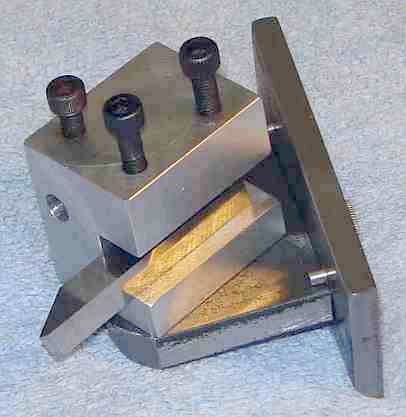
The backplate is HRS 2.5 to 3.5 wide, 1.5 high and 1/4 thick. I used 10-32 socket head fasteners throughout, Cleeve used 1/4". A clearance hole is needed in the backplate 9/16" from the bottom and centered. The bottom edge is beveled (about 45 degrees, leave 1/32 or so on the back edge untouched) on the front to allow tilting the jig about the rear edge in use. The pins are added later to facilitate setting the 10 degree relief angle.
The mounting plate is 2" wide, 1.75 long and 3/8 thick HRS. A hole is drilled and tapped in the center of the back edge to connect this plate to the backplate. A hole is drilled through the mounting plate 5/8 from the front edge; this to connect the toolholder to the mounting plate.
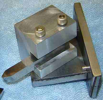
The toolholder is 1.25 wide, 1.5 long and 1.5 high. Cleeve used steel, I used aluminum because it is easier to work and I don't expect to wear the jig out from use -- if I do then the next block will be steel - or HDPE (a good option for builders who don't have a mill). The 1/2" deep tool slot is 3/8 from the bottom. The hole in the bottom is 1/2" from the side opposite the slot and centered front to back. Cleeve used 3 bolts to secure the bit in the holder, I thought 2 were enough (we all leave our thumbprint on our work). I set the angle of the toolblock to 60 degrees using a machinist protractor then scribed a line to allow setting the toolblock angle easily; other angles are sometimes needed (Acme, Whitworth) but these are infrequent in my shop so they will be set with the protractor when necessary.
To add a stop pin in the backplate, the mounting plate was tilted 10 degrees and locked with the screw. A 1/8 transfer punch was held against the top of the mounting plate at the desired level and used to mark the center of the hole for the 1/8 pin. The hole was drilled slightly under size then opened part way through to 1/8 (from the front side). A 1/8 pin was cut to length and the end tapered slightly then pressed into the hole to provide a stop at 10 degrees for the relief angle. Two pins are needed, one on each side.
 A guide is needed on the grinder rest, perpendicular to the side of the wheel and far enough out to allow the jig's backplate to pass so the bit can contact the side of the wheel. For external threading bits like the one shown the toolholder angle can be changed from +60 to -60 and the relief angle changed appropriately - then the other side of the wheel is used. When using the left side of the wheel it may be helpful to rotate the toolholder so its slot is on the right side. Alternatively, change only the relief angle and flip the bit itself over to use the same side of the wheel. Lots of ways to use it once you have the jig in hand.
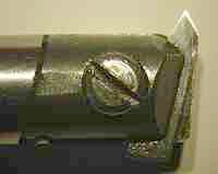
The sample bit shown in the parts picture is upside down to show the ground sections better. This is the bit I originally ground freehand, then cleaned up with the jig. It has done all my threading for 3 years and definitely needed sharpening, something I was avoiding because of the time it took the first time around. It took less than 10 minutes to resharpen it with the jig, most of which was learning how to use the jig and hand honing after grinding. Cleeve sharpens threading bits with the point on the left so they can thread closer to a shoulder, something I didn't think through when sharpening my first threading bit so the point on mine was centered... Cleeve also recommends some side rake to improve finish and shows how to do this easily and accurately, I'll try this on the next threading bit I sharpen. Finally, if the guide on the grinder rest is accurately perpendicular to the wheel then in use the bit can be aligned parallel to the face of the chuck -- more accurate than using a fish tail according to Cleeve.
Another detail on threading bits: the tip must be flattened or rounded to produce the appropriate width for the bottom of the thread. The natural thing is to round the end of the bit for the full height of the 60° angle. The tip's bottom relief is about 20°, the sum of the relief for the two sides. This is far more relief than needed, causing the tip of the tool to be weak and prone to break. To improve tool life, round or flatten the end with 8° relief - the tool will be much stronger and less prone to tip breakage.
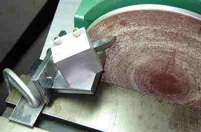
 The book provides information on how to make a nice boring bar type holder for inside threading and boring. I haven't made one (yet) but I did sharpen a regular Everede HSS insert for threading - something I had avoided for 2 years. Cleeve's jig is simply swiveled to 60°; there is just enough clearance when sharpening the tailstock side of the bit for the boring bar to miss the wheel, as shown in the picture. The boring bar is rotated 180° and the right side of the wheel is used for the other side of the bit (so clearance isn't a problem).
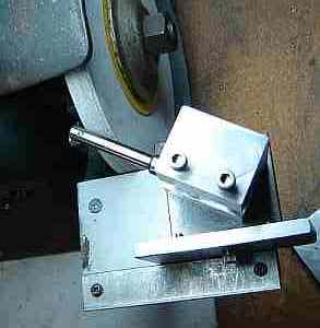
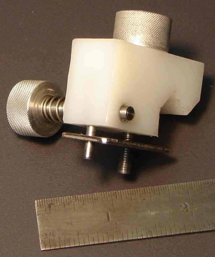
 The bit was extended from the bar while sharpening to increase clearance. This picture shows the result, with the bit set for threading. Note how the insert is held at an angle; this angle is what prevented me from using this bar for threading prior to building Cleeve's jig. This bar uses the small HSS inserts, only 100 thou wide.
"Screwcutting in the Lathe" is an excellent book that details how to use this jig to sharpen bits for internal threading (may need another simple part) as well as ways to make holders for threading tools, both internal and external, and a tool retractor to make threading easier. This book is well worth its modest cost if you do threading on the lathe.
For safety reasons, grinding on the side of the wheel is not generally recommended with bench grinders - the wheel isn't meant for this although Cleeve shows it in his book. I used the bench sander shown to rough the outside threading tool, then finished on the bench grinder. The outside threading tool takes a while to grind so roughing on the side of the wheel should be avoided. Another method I use is to touch the blank to the side of the wheel to produce a small area that serves as a guide for the major grinding. I then pick the jig up, match the flat to the front of the wheel and grind some off... then repeat this sequence until the bit is nearly done when I use the side of the wheel to finish up. This uses the circumference of the wheel for the major part of the grinding.
My internal threading bit is a tiny insert so that was done on the side of the grinder wheel in a few seconds; so little material was removed that roughing wasn't worthwhile. Resharpening threading bits with the jig is quick and removes little material because the jig reproduces the angle accurately. However, when the side of the wheel eventually becomes loaded with metal, realize that refreshing would thin the wheel and reduce its strength, possibly making further use hazardous.
Sharpening lathe and shaper bits in the home shop is an iterative process - grind some, check progress, grind a little more, check progress, etc. When hand sharpening it is common to have the angle slightly different following each check, leading to a "faceted" tool i.e. the tool shows all these slightly different angles. Often, when attempting to re-sharpen a bit we get the angle slightly wrong and end up having to grind more to compensate or recover. Using the jig allows setting it up by touching it to the non-moving wheel, tweaking the angle to get it just right before committing to removal of HSS.
This jig can accommodate most lathe bits with only minor contortions if you use a grinder rather than the disk sander shown above -- a grinder adds some freedom by allowing use of the circumference as well as the sides (see caution above) of the wheel. If the jig's mounting plate is flipped over you can scribe desired angles on it without losing the lines scribed for threading bits (or simply use a protractor). There are two degrees of freedom: rotation on the mounting plate plus rotation of up to 10 degrees for relief. In combination with using either the sides or the outside of the wheel most desired shapes can be accurately and repeatably ground. The key point is that, once set, the angles repeat nicely after picking the jig up to see how things are coming along.
I found the jig worked well in making dovetail cutters for my shaper. The cutter angle needed was 55° for a 60° dovetail so the angle was set with a protractor. The relief angle needed was about 7° so this was set with a gap gage on the normal relief pin. The nice part is the tools look professional (no facets) and they worked first time with no trial and error or fussing to get the angles right.
Looking at these two pictures makes it obvious that my jig has seen some changes in the 6 months that I've been using it. Most obvious is the hole for round threading bits as used by the Retracting Toolholder; the bore angles upward at 7 degrees to match the toolholder. The bolts that hold the square bits in place are longer to accommodate the 1/4" bits used by my shaper. And, the corners of the mounting plate have been removed to increase clearance for the grinding wheel. Not shown is a recess for the head of the bolt which holds the block to the support plate; this allows the jig to be moved through a larger angle when using the side of the wheel. (Plus, I re ground my threading tool per Cleeve's example to allow threading to a shoulder.)
If I were to make another jig, I'd move the block as far back on the mounting plate as possible while allowing 180 degree rotation and I'd shorten the mounting plate to match. Making the support plate and the toolholder narrower would improve clearance for the grinding wheel even more. These changes aren't needed for threading bits but add flexibility to accommodate sharpening other types of bits.
What follows are some thoughts on making and using threaded fasteners with standard 60° threads. Not the last word on threading, just what works for me.
Threading itself isn't difficult but it requires considerable concentration and attention to detail, especially while cutting your first few threads. It's best to practice on some scrap until you gain confidence in the process and your ability to execute it accurately.
I avoided threading for some time after getting the 7x12 then ground a threading bit by trial and error and used that until it got dull. I built Cleeve's jig to sharpen threading bits more easily (a big help), added DRO's to the lathe (helpful for setting the infeed), and most recently built a retracting toolholder for threading (to avoid winding the cross slide in and out for each pass). Although I still recall my first threading attempt and being doubtful the cutter would exactly retrace the thread each pass, I have now done enough threading that I am more confident it will follow the same path each time :-)
First, I try to choose a TPI divisible by 4 because it simplifies single point threading operations by allowing use of any (odd) number on the thread dial for sync. When given a choice I choose 32 TPI and use 6-32 or 10-32 machine screws; the next larger size I commonly use is 1/4-28. I have spiral point plug taps and also bottoming taps for these three sizes. My larger taps are from a standard tap set so only plug taps are available.
For the simple little items I build, 6-32 and 10-32 cover most of my needs, making it easy to keep a selection of types and lengths of machine screws. I've found it convenient to stock longer machine screws and shorten them as needed unless a large number of screws are involved. Shortening is easily handled with a small tool of 1/4" steel scrap drilled and tapped for 6-32 and 10-32; the length to be removed from the screw is put through the tool, the tool held in the vise and the excess removed with a hacksaw. The rough end is smoothed by applying the tool to the bench sander then the screw is advanced a half turn and the thin part of the thread is rounded with a small file. The sander slowly wears the tool away but a replacement is easily made.
Single point threading on the lathe is the best choice for a number of things, especially when the thread must be concentric to the shaft it is on. Threading with the minilathe requires: 1) installing the appropriate gears, 2) sizing the area to be threaded, and 3) the actual threading operation.
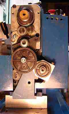 There are a number of charts available providing the gear setup for metric threads but most of my threading is imperial so all the needed info is on the sticker attached to the headstock cover. I use Richard Hagenbuch's threading banjo (pictured) and fine feed module to minimize the effort of transitioning between modes; Richard's plans for both are available (reproduced here by permission). By choosing to use mostly 32 TPI threads, my banjo remains set up for this making switchover quick and easy. One thing that makes gear changing easier is realizing that most TPI setups only use 3 gears and thus the idler gear tooth count is arbitrary - no need to change it unless the current idler simply won't fit - the banjo is particularly easy to adjust to handle many TPI's with the same idler. When installing the gears ensure there is a bit of clearance - some use a strip of paper in the gears to set clearance - else the gears can bind slightly which will cause the thread to be erratic (a so-called drunken thread). The gears should turn easily with no binding using the gear on the end of the leadscrew as a knob. The plastic change gears don't require lubrication making handling of the gears cleaner. Once the change gears are set up and spin freely, you can engage them when needed (lathe not spinning, of course) using the handle at the rear of the headstock.
The major diameter of the area to be threaded is found in the standard charts; I use charts printed from the LMS site, the chart for imperial lists major and minor diameters while the metric chart requires some calculation. Turn the area to be threaded down to the major diameter as provided by the chart. Use a file to chamfer the end at 45 degrees or so for about 1 thread. Calculate the thread depth: (major diameter - minor diameter)/2 ; this is the amount the CS will be advanced.
Standard threads are cut with a tool having a 60° angle and 10° relief, as produced using Cleeve's jig. The point should be rounded to handle the finest thread you expect to cut. The easy way to do this is to use a commercial screw as a gauge and hone the tip of the cutter until it fits nicely (the tip will likely snap off if left sharp). Tools sharpened in the jig are aligned properly if the side of the tool blank is parallel to the chuck - so a fishtail tool isn't needed, just use a parallel between the face of the chuck and the cutter body. The tip of a threading tool is relatively narrow and delicate so threads are cut using multiple passes, adding a few thou of depth per pass -- this also produces a better finish on the threads.
There are two basic ways to advance the cutter when threading: feed straight in (cutting on both sides of the V), or feed down the flank (cutting on one side of the V). Feeding down the flank generally is easier on the lathe and produces a better finish on the threads so it is almost universally used. There are two ways of advancing down the flank: set the compound to 29° (or 29.5° or 30°) and use the compound to feed the tool or use the cross slide to feed and, with the compound at 90° to the CS, advance the compound half the amount the CS is advanced. Cleeve suggests this second method, with the compound at 90° and after trying it I decided I liked it better than setting the compound to 29° so that is the technique described below.
I use a handwheel for most threading but especially when threading to a shoulder. The handwheel allows precise control of the stop point and avoids crashing the tool into the work or the chuck. On long threads I use power, of course. When the handwheel can't be used I sometimes resort to turning the chuck by hand for short threaded sections. My lathe sometimes turns the spindle rapidly for a half turn as the speed control is switched to OFF - one reason I prefer the handwheel for short threads.
Assuming you intend to cut an imperial thread whose TPI is divisible by 4 and having followed the above to set things up, you're ready to start. Apply cutting oil to the area to be threaded, as needed, throughout the process. Engage the drive to the leadscrew and verify that the carriage moves toward the headstock when the half nuts are engaged and the spindle is turned. Position the compound so the bit is over the CS (not extended out to the left since this can cause chatter). Bring the bit up to just touch the OD of the section to be threaded and set the CS dial to zero. Move the carriage to the right beyond the work until the threading dial is on any digit and engage the half nuts. Advance the CS by about 2 thou and use the handwheel to rotate the spindle and scribe a thread onto the work for at least several turns. Retract the CS by one full turn, release the half nuts, wind the carriage to the right out of the way. Use a thread gauge to verify that the expected TPI was cut. Assuming all is well, repeat the following until the desired thread depth (calculated from the chart) is reached.
Make an additional spring pass or two with no (or minimal) additional infeed to clean the thread flanks up. An alternative is to stop the single point threading process before arriving at the target depth and use a die to complete the threading process. Threading leaves a small burr at the top of the thread; turn the work at modest RPM and touch the threaded area lightly with a fine file to remove this burr.
When less than 5 thou from the calculated depth I test the thread with a commercial nut on each threading pass, stopping when the nut fits nicely or at the target depth (whichever occurs first). Then clean up as described above.
If your threading bit's point was sized for more TPI than the thread being cut, the V will be too narrow when you arrive at the target depth; advance the compound a couple thou and make another pass without changing the infeed -- repeat as necessary until the test nut fits. Note that if the compound is set at 29° you can't use this technique; you'll need a bit whose nose is rounded appropriately for the TPI being cut - meaning you must regrind the bit slightly each time you cut a different TPI.
The finish of the thread depends on the material as well as a sharp bit. A die may produce a better finish on some material. Similarly, using a thread restoring file may improve the finish.
Single point threads are concentric with the work (assuming the work was mounted concentrically). Cutting threads to near finished depth and then completing with a die works well - much easier on the die and requires much less torque. Particularly helpful on larger threads because they require so much torque that they may slip in the chuck. Plus, it helps keep the thread concentric with the work, something that may not happen when using a die without single pointing first. As usual when threading, use plenty of lubricant.
If the TPI to be cut isn't divisible by 4 then you can choose the numbers on which to engage the half nuts using information from the manual. Or, you can simply choose any particular digit (like 5) and always engage on that specific digit - I do this because it is easy to remember and works for all TPI, although it wastes a little time waiting for the number to come around.
Metric threading differs from imperial because the half nuts remain engaged when cutting metric threads and the carriage is returned by turning the spindle backwards. The threading dial on the 16 TPI leadscrew doesn't work for metric threads. Even lathes with a metric leadscrew require changing the gear on the threading dial for various threads - typically there are 4 small gears supplied for this. The key detail is that imperial threads are specified as turns per length while metric threads are specified as length per turn ... and this makes all the difference. The change gears supplied with the 16 TPI leadscrew lathe provide close approximations for the common metric threads; these approximations are close enough that the error shouldn't affect the fit to commercial metric fasteners - but check the fit before making several identical parts, just in case.
Click to Enlarge

I looked for a minilathe mechanical auto-stop but didn't find one that triggered so the stop point would be reasonably repeatable. Repeatability is needed when the auto-stop will be used for threading, my main use for it. Of course it is also useful for finish passes using fine feed to avoid a crash should you be distracted. This auto-stop works only for imperial threads while the more complex dog clutch auto-stop provides automatic thread pickup for imperial and metric threads.
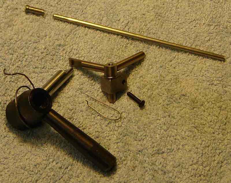 This design uses only a few small parts but requires careful fitting. It uses two purpose made springs, one in the trigger mechanism and another on the half-nut shaft's collar. The mechanism cocks when the half-nuts are engaged by pressing the normal lever; the half-nuts disengage automatically when the actuating rod contacts the mechanical stop, activating the trigger. All of the round material and spring wire are from scrap line printers.
Two 1/4" dia. standoffs, cross drilled for the 1/8" actuating rod are not shown with the other parts (I was too lazy to remove them since it required removing the carriage... again!). These standoffs have a 1/4" long spigot threaded 6-32 and the carriage is D/T in the opening behind the apron on each side - If you look at the pictures carefully you can see them supporting the rod. I threaded the end of a long 1/4" rod and then screwed it into one of the D/T holes, marked where the cross hole should be so it would support the rod in the desired orientation, then cross drilled and parted off.
The rectangular block (3/8x3/8x1/2) that supports the trigger mechanism has a small rebate milled out of one side so a single 4-40 screw can hold the block in place with the rebate preventing the block from rotating. 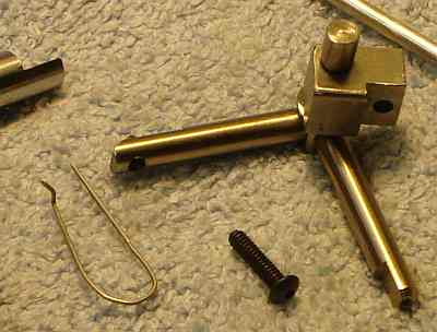 The rectangular block is drilled so a pin with a 6-32 thread on the end can hold the trigger mechanism in place.
The trigger pivot is simply a round with two flats milled 90° apart and a small shoulder near the bottom. Each arm has a spigot turned on the end, then pressed into a hole drilled in the center of the flat. Each arm has a flat milled near the outer end; one flat contacts the actuating rod. The flat on the other arm contains the sear, made from drill rod and hardened. The sear is 1/8" turned down on one end to press into a #36 hole drilled in the flat area of the arm. The sear has a flat filed on one side of the top with a slight undercut so it latches the arm on the half-nut shaft's collar securely. The end of the sear arm and the top of the sear were blended at an angle on the belt sander so they deflect and move smoothly past the latching arm. The hairpin shaped spring hooks behind the sear arm and pushes it away from the apron (see picture above), ensuring it latches as the half-nuts are engaged.
A latching arm is added to the collar on the half-nut shaft, 90° from the handle. A flat was milled and a hole was D/T 10-32. The round was threaded into this and marked so the flat could be oriented properly; it was cut to length and the flat milled to the center. A spring was fashioned to wrap around the half-nut collar 1.5 turns, hooking on the latching arm and to a pin added to the bottom of the apron.
The stop rod has a cap on the left end.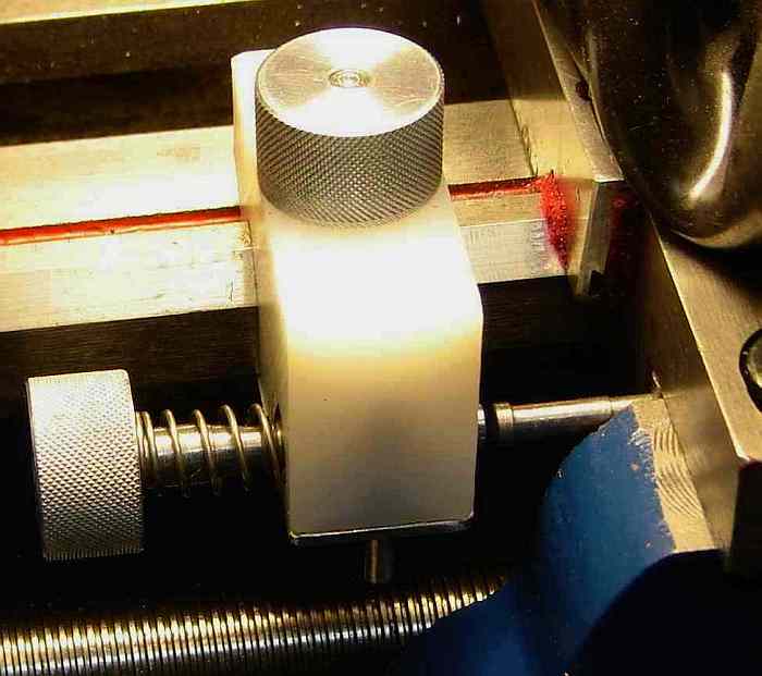 This cap is drilled such that it contacts the standoff just after the mechanism triggers and before the sear arm contacts the apron. Should something go awry and the half-nuts not release, this should avoid breaking the trigger mechanism.
The dovetails in my half-nut mechanism were not mating properly; the thin edge of the dovetail on the half-nuts was in contact rather than the flat. I filed the thin edge down to allow proper contact. This improved operation and made the gib on these dovetails easier to adjust.
The original half-nut mechanism includes a spring to give snap action plus ensure the mechanism stays open; I backed off the pressure adjustment for this somewhat (accessed next to the thread dial) to improve release by the trigger; it still holds in the open position properly.
Use caution with this auto-stop: if its operation isn't 100% reliable then it can cause an expensive crash. Spring force must be sufficient to release the half nuts reliably -- if it is marginal then eventually it will fail... so ensure the half-nuts move smoothly with minimal friction and check overall operation carefully.
Update: I managed to crash it but didn't hurt anything...this time. It was working great while making the micrometer stop. But when I tried to take an aggressive initial cut (10 thou) on the 1/4-20 thread the trigger released but the half-nuts didn't move. A deeper cut needs more force from the half-nuts and this increased the friction enough that my spring couldn't release them. The simple solution is to cut a runout groove before threading - this relieves the force on the bit allowing the trigger to release. I could use a stronger spring but would likely need a rubber stop for the latching arm to avoid hammering the half-nut mechanism. I now add a little upward force on the original handle with my finger to ensure it triggers cleanly; threading requires my attention anyway so this isn't a hardship. It's quick to make passes using the auto-stop + retracting toolholder (and it's fun to use them).
To manually release the half nuts, push the arm holding the sear. The original handle works normally when engaging the half-nuts but cannot release them - it takes a little while to get accustomed to this if you've done much threading with the original arrangement. To temporarily disable the auto-stop, unhook the spring from the pin on the bottom of the apron and wedge the trigger arm in the open position with a small piece of wood.
The auto-stop generally repeats +/- 2 thou but occasionally is off by up to +/- 4 thou. This limits how close to a shoulder the stop can safely be set. Surprisingly, carriage speed has little effect on repeatability.
Note that when using the auto-stop a runout groove is created automatically - it gets trickier if you don't want a runout groove. To avoid a runout groove you withdraw the tool just as the trigger trips; the retracting toolholder is helpful for this, plus it is best to run at fairly low RPM to make your timing less critical.
I initially used my combination carriage stop and dial holder made some time ago. Fine adjustment of the stop point was awkward with this so I built another stop (from HDPE) with a coarse (20tpi) micrometer type adjustment. It was about as much work to make this stop as it was to add the auto-stop...but it greatly simplifies setting the stop point: with the lathe OFF set the carriage at the desired stop point, engage the half nuts, move the stop so it touches the rod, lock it in place, and turn the micrometer adjustment in until it triggers.
I've always threaded to a shoulder using the hand wheel - it's slow but safe. It takes blind faith to thread to a shoulder at 300 RPM but it works and threads cut at higher speed seem smoother. The combination of auto-stop and retracting toolholder requires a different routine, which gives threading a much different "feel".
If you have a comment on this site or its contents,
click here.