* GadgetBuilder.com *
Last Modified:
SpeedFan is a stable, reliable program which provides fan speed control using the existing facilities on the VNF4 motherboard for temperature readout and control of power to fan connectors. On startup SpeedFan scans the SMB and ISA busses, automatically finding all sensors on the motherboard. On the VNF4 (and many other mobo's), SpeedFan locates some inputs which don't have sensors attached - the values read from non-sensors are nonsense :-) The user can decide which inputs are not useful and adjust SpeedFan's configuration so these values are not displayed.
SpeedFan has a good HELP document to guide the new user through configuration. Configuration is more complex than one might expect and some parts may not be intuitive so screens showing the setup for the VNF4 are provided below. The following material may help new VNF4 owners configure SpeedFan more quickly than they otherwise would.
A very helpful feature in SpeedFan is the charting capability. SpeedFan runs periodically in the background and stores values from variables; these values may be charted any time and show values sampled over the last 10-30 minutes -- the actual time covered by charts varies in a way which I haven't been able to predict. Samples seem to be taken at 3, 6, or 9 second intervals.
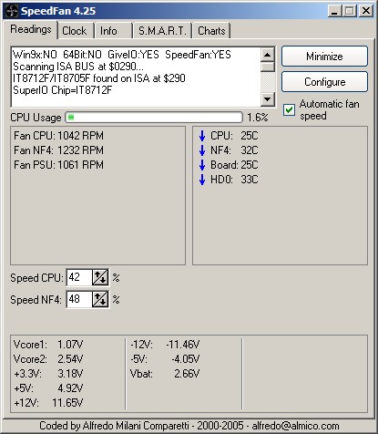
Prior to configuration for a specific system, SpeedFan displays all the temperatures, fan speeds and voltage readings that it finds. This simplifies initial testing as well as further configuration - everything available is visible (along with a few items that aren't really available so they produce erroneous readings).
It is reasonable to get manual fan control working for the CPU as a first step in using SpeedFan; generally, SpeedFan's default settings do this automatically (fans run at 100%) although it is wise to verify because BIOS choices may affect the situation. To verify, go to the Configuration/Advanced screen and enable "Software control" for the CPU fan (PWM1 in the VNF4) as described here. With PWM1 set to "Software controlled", use the up/down controls for the first fan in the list on the main SpeedFan page to change the CPU fan's speed. Running the setting down should lower the fan speed displayed by SpeedFan; the labeling will be generic until it is configured but this initial setup and use is reasonably intuitive and should inspire a bit of confidence in SpeedFan.
The remainder of this document covers configuring SpeedFan for the VNF4 although the material may be generally useful with other mobo's. Initially, non-existent sensors are eliminated from display on the main screen. Sensors and fans are renamed to make their function easier to remember. Then, the CPU fan is configured so its speed is automatically adjusted to stabilize CPU temperature. An additional fan can be configured for control by analogy with the method used for the CPU fan. The VNF4 provides a third fan speed readout but only controls two fans.
The following descriptions are ordered according to the tabs on SpeedFan's Configure screen, proceeding from left to right.
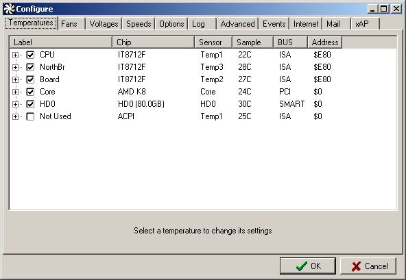
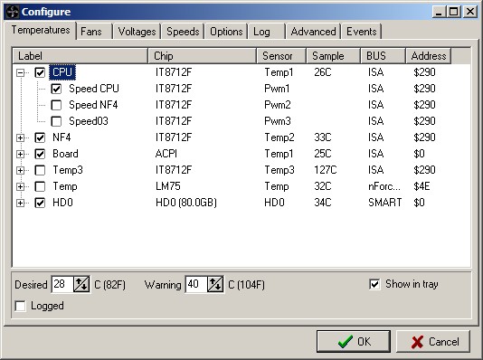
The Configure/Temperatures screen allows un-selecting sensors (e.g. Temp3) so they won't be displayed.
In addition, sensors may be renamed so it is easier to remember what they are measuring; this has been done for the VNF4 in all screens shown in this section. In order to change the name of the selected sensor, click on the name and wait for a second or two, click again and wait for the name display to change slightly (from a dashed box to a solid box), indicating it is ready for input; SpeedFan only runs every 3 seconds so there is usually a slight delay. The selection process is a little unusual in that it is two single clicks -- a double click usually won't select it. Use Drag+Drop to re-order the sensor list if desired.
The VNF4's CPU temperature is measured by a diode, probably on the CPU because it reacts quickly to changes in CPU load. The NF4 temperature is measured by a resistor located "near" the chip; it reacts much more slowly to changes in load or cooling fan speed. The "Board" temperature seems to read internal case temperature; Chaintech has not provided info on this sensor's location.
To set the "Desired" or target temperature click on the "Sample" column for the selected item, CPU. If you set the target temperature lower than is possible to achieve with the fan at the highest speed that you configure (done later) then the fan will remain at the highest speed. If you set target temperature so the fan can maintain that temperature at the lowest speed allowed then the fan will remain at the lowest speed. So, it takes a little experimenting and some experience to choose appropriate values. With the VNF4 and a Winchester CPU, the target temperature will typically be 24C to 30C, depending on ambient and the fan speed range you select, of course. A target of 28C is a good starting point which can be adjusted later as you gain experience with SpeedFan and your system; my system typically runs 26C so the fan stays at the low limit unless the load increases.
Set the "Warning" CPU temperature to a value which should not be reached in normal use but which is well below the damage point. The associated fan(s) will go to 100% speed if the Warning temperature is exceeded so the fan noise may provide a warning of sorts. SpeedFan can also provide an on-screen alarm and/or a beep via Event settings.
To associate a sensor with the fan for control, click the "+" to the left of the sensor to show the drop down list, then click on the desired fan. Verify all sensors in this manner to ensure that only the desired sensor(s) are controlling the fan. It is possible to configure more than one sensor attempting to control a fan which is generally not what is desired.
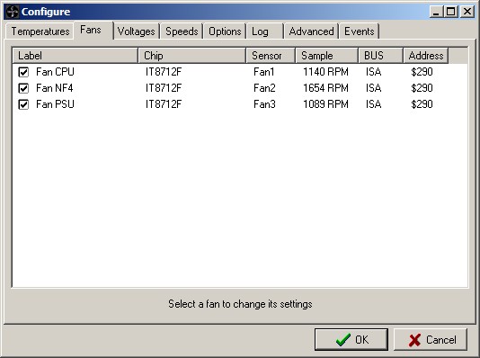
The Configure/Fans screen allows selecting whether a fan's speed is displayed on the main screen. Fans can be renamed here using the same selection technique described earlier.
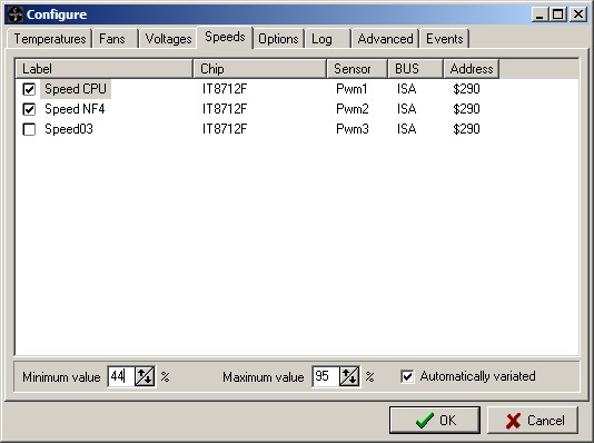
The Configure/Speed screen allows changing the name by clicking on the name twice then typing the new name (as above).
To change the speed range for a fan, click on the name once then use the up/down buttons to change the Minimum value and the Maximum value; these are the percentage of time power is applied to the fan (i.e. PWM % ON time) so they change the range of fan speeds available for that fan. Check the "Automatically variated" box to enable automatic control (there are more steps needed to completely enable auto control). When setting the minimum value, avoid setting the value so low that the fan stops -- it often takes a large change to restart a fan after it stops. Verify the minimum run speed using the main screen by un-checking "Automatic Fan Control" (all fan setup must be completed prior to this, including "Advanced"); use 70% for the minimum temporarily until you can actually check (most regular fans will run to 45%, some small chipset fans will stall at 65%).
As a safety measure, SpeedFan will apply 100% when the controlled temperature exceeds the Warning temperature you set. The maximum speed is generally set at the highest value which does not produce objectionable noise.
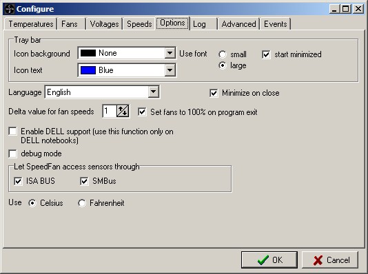
The Configure/Options screen Allows setting several options which are self explanatory. However, the Delta value for fan speeds is actually the loop gain for the control system(s) used to regulate fan speeds. My opinion is that this should be set to the lowest value available to provide the best speed stability.
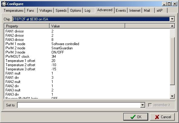
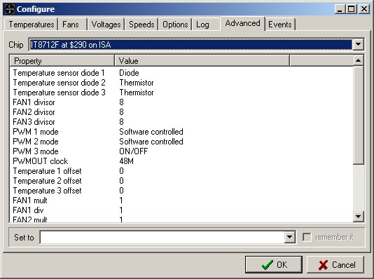
The Configure/Advanced screen allows the VNF4 user to configure the IT8712F chip which does the actual fan control. Most of this chip's configuration is done by the previous screens so the VNF4 owner need only select which fans are to be controlled. Use the drop down menu to select the IT8712F as shown and then select the value for PWM1; set it to "Software controlled" if this isn't set already -- this is what allows SpeedFan to adjust the CPU fan's speed by setting registers within the 8712F. Don't forget to select "Remember it" after making the selection. Select "Software controlled" for only the CPU fan initially so you only have one thing to watch while you work out any kinks.
In my system SpeedFan controls another fan to cool the NF4 so PWM2 is Software controlled -- a less common scheme so you most likely won't do this.
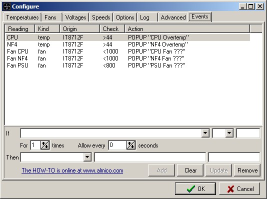
The Configure/Events screen provides an intuitive setup for events which are to be announced by a balloon dialog, a beep, or execution of a program. This alerts the user when a possibly damaging condition occurs (e.g. a fan failure or a sensor over-temperature indication). Events are a relatively new feature so I haven't much experience with their configuration but they seem simple to use and work as expected when tested. The approach used is flexible and sophisticated -- a significant programming effort.
In v4.25, if no events are programmed then an error appears at the end of the list of sensors found on the board. Once you program an event then this error disappears.
Once you choose "Software controlled" SpeedFan is controlling the fan speed and YOU are controlling SpeedFan. Immediately verify that the fans are spinning and that temperatures are not rising unexpectedly (if they are, go back to the Advanced screen and change PWM# back to On/OFF). Use the Speed % up/down controls on the readings screen to adjust the fan speeds if needed so that the fans are providing the necessary cooling -- control is not automatic, yet. The Winchester CPU's generally heat up slowly even with the fan off so if you're fiddling with only the CPU fan there is plenty of time to check and correct for rising temperatures.
Next, check the box for "Automatic fan speed" on SpeedFan's main page. Within 3 seconds the "Speed CPU %" should show a value within the control limits you set earlier. If the CPU temperature differs from the Desired CPU temperature then the Speed % should begin to mosey in the appropriate direction if it isn't already against the limit. You can disturb SpeedFan's control by using the up/down % controls for the fan on the main page; SpeedFan will correct the value to a limit if you try to move beyond the specified limits or Speedfan will begin to move the speed in the appropriate direction to correct the disturbance you introduced.
Once you're sure SpeedFan is controlling fan speed properly, check the lower limit setting of the controlled fan(s) to be certain that they don't stop. This is easily done from the main page by unchecking "Automatic fan speed", then adjust the speed downward while monitoring the fan. Be sure your "Minimum value" is larger than the fan stall value by at least 5% by re-visiting the Configure/Speed screen.
While SpeedFan is one of my favorite programs it does have some wrinkles which could be improved -- easy to say when I'm not doing the programming, of course :-) Because I've used and explored SpeedFan so much I have developed a wish list of items I would like to see improved or added:
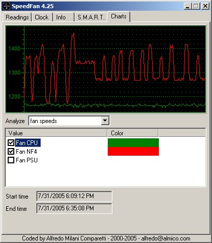
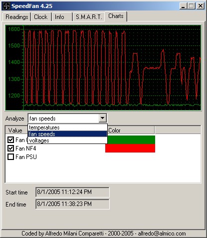
SpeedFan is often speed unstable controlling fans despite my best efforts; one solution is to raise the "Minimum value" until the fan speed stabilizes; the stable point is somewhat dependent on ambient. Unfortunately, this tweaking is what I expected SpeedFan to do automatically. The above screen shows the results of adjusting the Minimum fan speed, where the stable section near the center is with the fan above the critical value. In general, fan speed is seldom stable unless the fan is at the min or max limit; this is probably caused by the delay in sensor response and cooling delay vs SpeedFan's control algorithm. The fan speed oscillations are distracting because they make the fan audible periodically in my system.
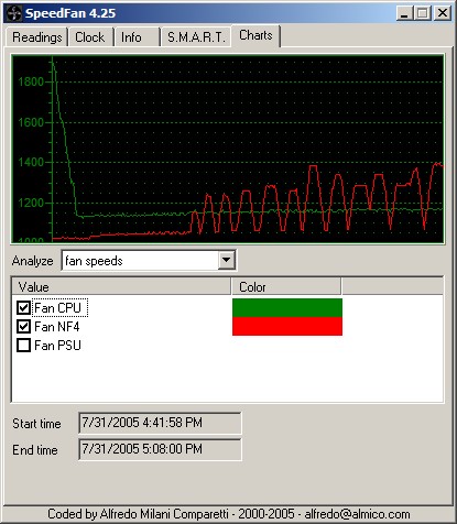
My conclusion, based on numerous experiments on my system, is that SpeedFan's control loop gain is too high when the error(difference between the measured and target temperature values) is small and conversely, the gain is too low when the error is large (e.g. at startup the system is 5C below Desired but the fan speed is high, so fan speed should be lowered rapidly). The control loop gain is set by the "Delta value for fan speeds" on the Configure/Options page. In this example, changing Delta from a gain of 5 with large oscillations(on left side) to a gain of 1 reduces the amplitude and frequency of oscillation -- a classic feedback control system response. Temperature was stable within 1C throughout the period shown. Here is the system at startup, showing part of the slow CPU fan rampdown and the startup of NF4 fan instability.
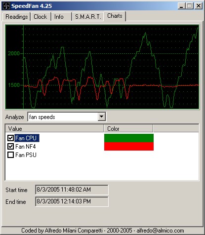
Here is another experiment, showing speed instability with both fans. Temperature is generally stable within 1C but note that the NF4 readout quiets (for no apparent reason) and the NF4 fan speed oscillations disappear -- however, the temperature is 33C while the Desired temperature is 32C, i.e. things are stable but with a constant error value (SpeedFan's control algorithm seems to need a bit of noise to operate on, else it doesn't control). These two screenshots also illustrate the peculiarity in the chart times with SpeedFan (mentioned earlier) -- the ending times are only a few seconds apart (as quickly as I could do it) but the start times are 12 minutes apart and the charts clearly cover different periods, as shown by the point on the two charts where the temperature and fan speed stabilize. The charts remain very valuable for system analysis but one has to be alert when interpreting them.
Perhaps the simplest way to reduce gain for small errors would be to add a counter for each fan. IF (Measured temperature - Desired temperature) is greater than 1.5C then zero the counter for this fan and proceed as original (i.e. move the fan speed by one Delta) ELSE bump the counter for this fan in the appropriate +/- direction and, IF the magnitude of the counter is greater than 5 THEN zero the counter for this fan and proceed as original (i.e. move the fan speed by one Delta). The goal is to reduce the gain (= number of increments per minute) when the error is less than 1.5C and this is accomplished by counting the number of potential increments when the error is small, acting on only every 5th one. Naturally, there are many more details needed to implement this plus some testing to find whether 5 is an appropriate gain reduction. Note that when the increment direction alternates +/- it will take more than 5 time periods to cause a change, a desirable result since the error is very small.
A different (similar but more complicated) way to improve speed stability would be to eliminate the setting for "Delta value for fan speeds". Instead, use Error == (Measured temperature - Desired temperature) = Delta. This would cause the gain to be larger when the error is larger and decrease proportionally for smaller errors. To provide stability for small errors: IF Error is less than +/- 1.5C THEN sum the signed Error value and when this sum exceeds a user settable magnitude (range=2 to 30C) then increment the fan speed control register in the appropriate direction and set the contents of the summer to zero -- this would reduce gain by a factor of 2 to 30 compared to the existing setup. Readers familiar with process control will recognize this as a simplistic form of Proportional/Integral control. The expected result would be rapid response to large errors and slow movement in the correct direction to reduce small temperature errors, where low level noise in measurements would be integrated out rather than initiating instability. While the algorithm would be somewhat more complex (a summer and a user settable magnitude (= loop gain) would be needed for each fan) stable speed control should be easily achieved for most any cooling setup. Separately adjustable gain for each fan control loop would ensure that boards like the VNF4, where the sensor response speeds differ considerably, would be accommodated. One drawback is that the user might have to set the gain for each loop, although reducing gain should oscillations occur is not a difficult concept to explain.
Another alternative (sort of an end run around the control algorithm problem) would be to allow SpeedFan to set the 8712F's SmartGuardian registers as dictated by the user. SmartGuardian provides smooth control of fan speed with no processor load (the algorithm is implemented in the 8712F chip). SpeedFan is already aware of SmartGuardian to some extent.
This graph illustrates how SmartGuardian adjusts the fans to control the temperature 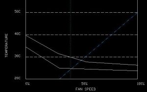 . The line which slopes up to the right is SmartGuardian's temperature vs fan speed characteristic. The lowest curved line is the CPU temperature vs fan speed as measured on my system. The upper curved line is a hypothetical curve for a higher ambient situation. The point where the SmartGuardian line intersects a CPU/fan line is where the fan speed will stabilize for those SmartGuardian settings. As ambient increases, the fan speed and temperature will increase since the new intersect point will be higher and to the right; SpeedFan's feedback algorithm will hold the temperature at the setpoint until it cannot do so with 100% PWM. The vertical dotted line at 40% PWM is the area below which fans often won't start turning; using SpeedFan, I keep the minimum speed at about this point. SmartGuardian has the logic built in (if the BIOS is programmed properly) to apply full power for a short time to start the fan, after which the fan will usually continue running down to about 30%.
Another possibility for SpeedFan: implement a SmartGuardian type control algorithm. This is conceptually simpler because it isn't a normal closed loop feedback control system, subject to Nyquist type criteria to avoid oscillation. It simply requires minimum and maximum temperatures in addition to minimum and maximum PWM%'s. Control is handled by ramping the fan speed through its range in proportion to the measured temperature, i.e. when the temperature measures half way between min and max, the PWM% will be mid way between its specified min and max. If the user chooses the values correctly then the temperature will stabilize somewhere in the prescribed range and will move a bit in response to changes in ambient (as noted above) and system load. The user can select the stabilization temperature empirically by adjusting the min/max points; unlike the closed loop approach, the user can't specify the desired stabilization temperature explicitly plus the temperature regulation is much less strict (not a problem in this application). This approach might "hunt" in a small range but shouldn't oscillate between the PWM% limits as the present approach often does.
So, there are a number of ways to address fan speed instability, with various amounts of programming effort to write and debug. My hope is that Alfredo will find the time and energy to address this issue.
Using SpeedFan to evaluate SmartGuardian's operation I encountered problems with both. With "Manual" fan speed selected in the VNF4 BIOS, the user can set the min and max temperatures corresponding to fan start and 100%; I used 20C=min, 50C=max and the CPU stabilized at 28C. The VNF4 BIOS configuration of the 8712F turns the fan OFF when the temperature is below the low limit -- this seems like it shouldn't happen if the low end hysteresis is set properly. SpeedFan makes it difficult to determine what is going on because it sometimes reads the speed as 650 rpm and sometimes as 100,000 rpm (clearly not a sane value, and one which SpeedFan should ignore, perhaps substituting zero). The BIOS doesn't provide for setting the hysteresis at the low temperature point so it is unclear whether this is used nor can I tell by examination due to the readout problem with SpeedFan; I haven't opened the case to watch the fan (yet), the ultimate way to tell if the fan keeps stopping and possibly has trouble restarting. The 8712F has a complex arrangement for controlling fan speed based on temperature, where the control parameters are loaded into the chip's registers; it is possible that these registers aren't properly initialized in the VNF4 (or any other machine's BIOS) causing unexpected problems with fan control.
Preserving the chart selections while SpeedFan is running would be helpful; no need to preserve them between starts. I frequently fiddle with SpeedFan's configuration (it is so easy to do) but often have to re-select which items to chart when I do this.
A problem with using the Fan3 connection to control the NF4 fan is that this connector defaults to OFF in BIOS so this fan doesn't run until WinXP starts SpeedFan. When running BIOS or BootitNG the fan remains OFF so the NF4 temperature climbs -- seems like a bug in v4.0 BIOS, perhaps Chaintech will fix it in a future release, along with lowering the SmartGuardian temperature setpoints available in BIOS.
There is an inconsistency between the VNF4 board and SpeedFan on fan ID's 2&3 :
Board Lettering vs SpeedFan
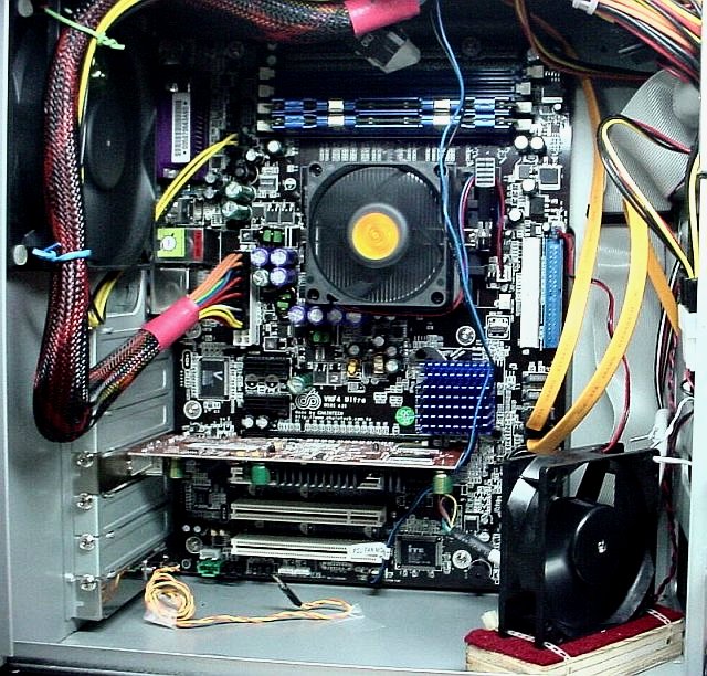
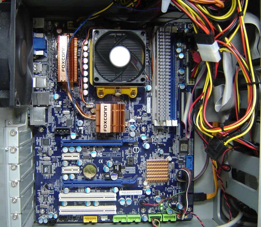
In this picture, the chipset fan is plugged into the connector labeled "Fan3 Case Fan" so it can be controlled by SpeedFan. The blue/black wires running to the bottom Fan2 connector allow reading the speed of the Sonata's PSU fan.
I tried the "SmartGuardian" fan control feature of the 8712F, available in the V4.0 BIOS. It ramps the CPU fan more smoothly than SpeedFan but does not allow selecting the temperature point low enough for my taste. Perhaps Chaintech will fix this in a future BIOS release.
Last Modified:
NOTE: Fortunately, SpeedFan is working out OK... As of Late December '08: Foxconn Support insists that the constant +40C reported by Fox One is correct regardless of CPU load or fan speed. They suggested I contact AMD since they used AMD's code in their BIOS; I believe Foxconn introduced a bug while adding AMD's code but they refuse to consider this possibility, even though there are several reports of the 40C issue in the Foxconn Forum.
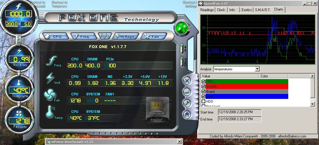
My VNF4 board died and a replacement Athlon 439 type board was not easily available so I replaced it with a Foxconn A7DA-S board, AMD 4850e, and 2GB of Corsair DDR2 memory in December 2008. The A7DA-S board is currently fairly new so the BIOS (81BF1P05) doesn't handle temperature readout or fan control properly. Fox One, Foxconn's program to configure the processor from Windows always reads the temperature as 40C, as does BIOS. This constant temperature reading apparently prevents the SmartGuardian function in our old friend, the IT8712F chip, from controlling the fan speed properly. Best guess is BIOS doesn't initialize the IT8712F (actually the IT8716F, a newer version) properly. Other A7DA-S owners have also reported constant 40C readings from BIOS and Fox One in the Foxconn Forum so I'm not alone on this.
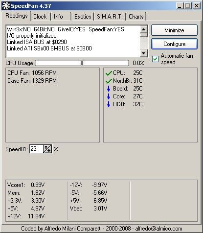
I installed Speedfan on the A7DA-S and it found several temperatures but some were biased by +15C, i.e. they read near 40C but, unlike the Fox One readout, they changed. The k8 Core temperature is biased by about -20C. Speedfan can offset temperatures for calibration so this allows Speedfan's display to make sense. My rough calibration method is to note the readings on startup and ensure that they are only slightly greater than room temperature, or about 20C. The basics on configuring and using Speedfan are covered in my earlier tome (above) on Speedfan setup for the VNF4 so I used that to recall how to use Speedfan since I haven't used it to adjust anything for years now. Fox One's temperature is always 40C while SpeedFan's chart shows that all reported temperatures vary frequently; I ran WPrime_155 twice in this test and Fox One showed 40C throughout. The blue line in SpeedFan's chart is K8 core temperature as reported by the 4850e with +20C added because of the Brisbane temperature reporting issue (perhaps should add +24C).
Speedfan shows all three 8712F temperature readings seem to be from legitimate sensors so I assigned names to them by guessing what they're measuring. To make a reasonable guess as to which temperature represented the CPU I tried adjusting the 8712F's PWM1 and found it controlled the CPU fan (lucky guess). I set this fan to 0% PWM, ran WPrime_155 to load the processors, and noted which temperature changed most. Then I felt the NorthBridge cooler and found it slightly warm to the touch so I assumed this was the next highest reading and the lowest reading shown I assumed is board/case temperature. (I submitted a ticket to Foxconn Support noting the readout problem and asked for information on what the sensors are reading; they didn't provide info on the sensor usage and insist that Fox One's reading of 40C is correct.) I found that the NorthBridge temperature is affected by the CPU fan so I use CPU, Core and Northbridge to control the CPU fan -- I may add an internal case fan for the NorthBridge eventually. Not shown in the pictures is that the K8 Core temp also required a +20C offset to make sense ; Core Temp 0.99.3 also reads the raw K8 temp as near 0C so this is a wrinkle with the 4850e(the well known Brisbane core temp error, apparently).
A peculiarity noted with my AMD retail CPU fan on this board is that even when the PWM is set to zero with Speedfan the CPU fan continues to spin slowly. I stopped it with my finger (carefully) and it stayed stopped for a few seconds and then restarted. Hard to say whether this is intentional or something about 4 wire fans; the older 2 and 3 wire fans required about 50% PWM to start. I set the PWM limits for the CPU fan at 10% to 55% (at 55% the fan becomes audible); by experiment I found that 40% is enough to keep the 4850e cool under high loading.
Here's my Speedfan setup for the 8712F:
PWM1 is now Software controlled rather than SmartGuardian controlled although I expect that it is SmartGuardian controlled out of BIOS until Speedfan takes over and adjusts the 8712F. The Fan divisors and multipliers were adjusted to get sane readings from my fans but the fan speed readouts on this board function poorly with Speedfan, reading strange values occasionally and then reverting back to reasonable. This makes the fan speed charts look peculiar but Speedfan's speed control seems to work OK despite the BIOS oddities. The A7DA-S uses the newer IT8716F chip rather than an IT8712F so it is possible that SpeedFan needs to handle this chip differently and this is causing the fan speed readout problem??? My system uses an Antec supply which has a readout of fan speed; this worked fine with my previous mobo but Fox One doesn't read it at all (although it does read the CPU fan nicely) while SpeedFan's reading is erratic for both fans.
Should Foxconn update the A7DA-S BIOS to fix the fan and/or temperature issues I'll revise this page, although I don't have much hope that they will solve this problem.
The fan control issue is more of a problem than I realized initially. I use BootitNG to image my system and this runs prior to XP startup so it relies on BIOS to control the fans. Imaging can take some time so with BIOS not controlling the fans properly I notice the temperatures shown by SpeedFan after imaging are elevated. Since my 4850e is fairly low power the temperatures remain safe but this could be an issue with a Phenom.
Other than Foxconn's unhelpful attitude on the temperature readout and BIOS fan control issues, I like the Foxconn board better than any of the other mobo's I've built. The A7DA-S manual is the best I've seen, very clearly written with good illustrations and it actually covers points that caused questions on other boards I've used. The A7DA-S board is nicely laid out and well constructed, plus the connector and part designations are easily readable. It uses 9 standoffs so it is well supported. The on board video is fine for my use and the 4850e's low dissipation complements this nicely. The only drawback so far is that I need a serial port for a legacy program I support and haven't found a bracket with a long enough cable to reach the COM1 socket on this board. Here's a picture of my A7DA-S in my old Sonata case.
Update: Since moving to Win 8 the built in fan control, probably SmartGuardian, works well; the fans are quiet and the CPU temperature is well controlled so I no longer need SpeedFan.
If you have a comment on this site or its contents, click here, scroll down and click again. Using this single link point reduces spam.