* GadgetBuilder.com * © 2012 by John Moran
And Other Miscellaneous Mods
Last Modified:
I started with a hacksaw, advanced to a Sawzall and finally purchased a HF 4x6 bandsaw. As with many Asian tools, it is good value for the price but needs a little TLC in order to increase its ease of use and performance. The blade which came with the saw felt sharp but didn't cut worth a darn. I fiddled with feed pressure and blade speed but finally replaced it with a Morse blade from Metal Mania and was very impressed with the improvement.
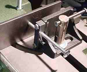
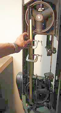
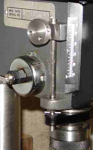
The first actual mod was adding an extended bolt with a Tommy bar (picture above) to simplify locking the movable vise jaw to the table. The original setup used a wrench which was never around when needed so this solved that problem nicely. This simple mod makes using the saw easier and is done by most owners shortly after purchase. Keep the Tommy bar short so it won't interfere with the blade.
 Another common mod is to drill a hole in the movable jaw to take a jack screw, allowing the left end of the movable jaw to be spaced away from the fixed jaw by the proper distance to allow clamping a short item. I decided against this approach because of the time needed to turn the bolt in or out to set the distance. Instead, I added a cam release for the bolt; when the cam is released the bolt may be pushed or pulled through the hole freely. When the cam is actuated the bolt is held by the threads and may be adjusted by rotating in the normal manner - see the picture at the top of the page.
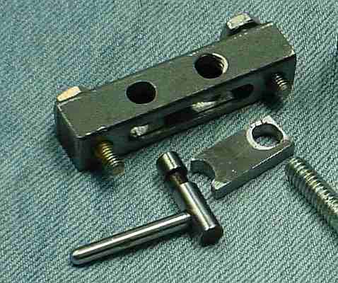
The internals are crude but work well. I milled a slot 0.440 deep in a length of 1/2" steel bar stock. This part was drilled and tapped for the 1/4-20 jack screw and a second hole 1/4" in diameter was drilled to hold the cam. The sliding lock was cut to size, inserted in the slot, marked with a transfer punch and drilled. It was inserted into the 1/2" bar and then tapped in place so the thread would match the previously tapped hole.
The bottom and sides of the threaded hole in the 1/2" bar were milled away to allow the lock bolt to drop down and clear the threads left in the top of this hole. The top of the threaded hole in the sliding lock was milled similarly, leaving threads in the bottom section. A cam was cut from 1/4" drill rod in the 3 jaw chuck by padding one jaw with 0.060 aluminum; the cam is slightly wider than the sliding lock it actuates. The cam was cut to length, cross drilled and tapped 6-32 for the handle. I oriented the handle with respect to the cam so the threads engage with the handle up but it could be done with the handle down, of course. The cam was hardened by heating it red hot and quenching in oil (not really necessary since this cam doesn't generate much force).
The sliding lock's lower end was adjusted with a round file so the lock releases the bolt in the down position and engages the threads in the up position. The bar was drilled to clear the 10-32 mounting bolts and the movable vise jaw was d/t to match. Assembly is obvious but not shown is a short helical spring wedged into the space above the sliding lock to prevent the cam from rotating due to the handle's weight. The cam is retained by the sliding lock which always engages a low section of the cam.
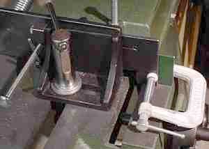
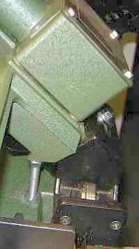
The vise doesn't always get a perfect grip on work and I was concerned that eventually something would twist, grab the blade and snap it. I looked around on the net and found that Frank Hoose had added an extension to the front jaw of the vise, similar to what I had in mind but MUCH larger. My goal was to provide support on both sides of the blade so the work couldn't swivel if the vise's grip loosened. I added a short piece of angle iron on the other side of the blade, as shown in the picture, secured to the saw by a 1/4-20 hole d/t into the casting. I was also concerned lest the cutoff move along and jam in the space between the blade and my new support (again, breaking the blade) so I left only 1/16 between the blade and the support - it takes a little while for the blade to stop after the power is automatically shut off.
As shown in the picture, a "C" clamp is easy to use to further secure short pieces being cut. The bandsaw is more versatile than I realized, especially when the ability to more securely hold small pieces is added. Roughing out work like this is faster than milling although milling follows to finish the profile properly. A side benefit is that the bracket close to the blade provides an improved estimate of where the cut will occur when positioning work.
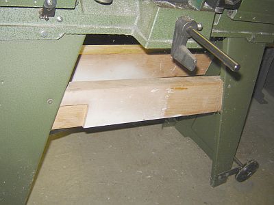
The sheet metal frame/legs of the saw are overly flexible. Easy to improve with a couple pieces of scrap 2x4 used as braces. Cut two pieces 24" long so they fit between the legs about 5" below the cast Iron saw base. Add a piece of masking tape on each leg 5" down to aid marking out. Hold one 2x4 section between the legs aligned with these marks, see the picture at right. Mark a line on the 2x4 along one of the legs then use a hand saw to make a kerf 1/2" or so deep, enough to accept the folded metal edge of the leg without touching the bottom of the kerf. Hold the 2x4 back in position with the folded edge in the kerf, align the top edge of the 2x4 with the tape and mark the other leg. Make a similar 1/2" deep kerf just outboard from the line. Drill a small hole in each leg an inch or two below the tape then use wood screws to secure the brace. Do the same for the other side. This is quick to do and will stiffen the frame and legs considerably. Add a piece of plywood across these parallel 2x4 braces to hold a sawdust collection box.
Blade alignment on my bandsaw was OK but not as good as it could be. There were two issues: the blade would occasionally pop off the wheels during a heavy cut and the cut had a slight angle vertically, requiring facing several extra thou from the end of a round after cutting.
 The wheels were not co-planar by quite a bit, measured as shown (using a straight edge just inside the blade). I cobbled together a temporary straight edge from an aluminum extrusion and an 18" SS rule - this allows placing the straight edge across the wheels while the blade is in place since blade tension could affect alignment. The misalignment was fairly large so I added washers as shims under the worm drive box to make the wheels co-planar. This was done by trial and error and I noted that too large a shim causes the blade to move away from the shoulder on the drive wheel as tension is added. The tendency for the blade to pop off the wheels is much reduced but it will still very occasionally jump off under heavy load - now considered a safety feature :-)
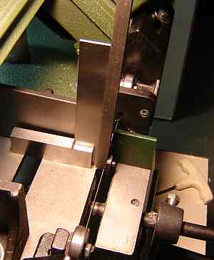 The vertical angle was mainly caused by the blade not being perfectly vertical in the cutting area, measured as shown. I used a holder for a carbide insert (positive type, no angle to the seat) clamped to the blade and compared to a square. The ball bearing guides which contact the sides of the blade were not snug against the blade so adjusting them brought the blade much nearer vertical. Filing the guide holder nearer the motor, where it contacts the frame, brought the blade to vertical. The cut is now vertical and facing need only remove the roughness left by the saw.
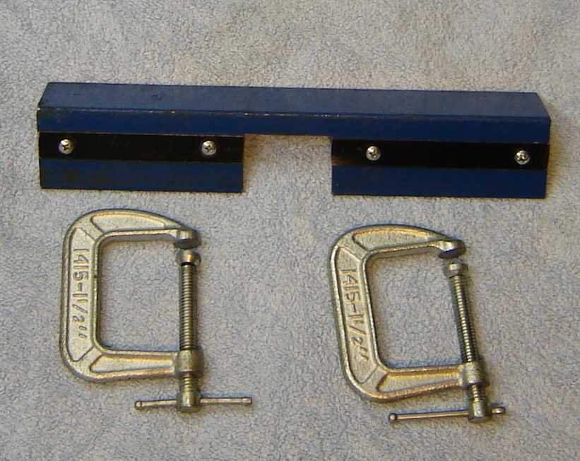 It's easy to build a fixture to align the ends of a bandsaw blade for brazing. A length of angle iron with a section removed in the center plus a piece of package strapping screwed down for a guide is all it took for mine. For simplicity I hold the fixture in a vise and secure the blade in place with the C clamps shown.
To make the scarf I use the round wheel on the belt sander by setting the angle of the miter to 60 degrees. I use a long wooden wedge cut to about 10 degrees pressed against the miter, extending out within 1/4" of the wheel. I hold the blade against the wedge and push the miter so it forces the wedge sideways toward the wheel. With the wedge providing support close to the wheel it makes a nice scarf. Folding the blade back on itself for scarfing worked OK but it was easier to do one end at a time - they match fine because the angle is set by the miter/wedge to be 20 degrees, the angle suggested on one site I found. It takes a little fiddling to grind it to length so the teeth match properly at the joint.
Clamp the ends in the fixture so they overlap in the center of the opening, being careful not to touch the ground area of the scarf since any dirt or oil will weaken the joint. Let a few thou of the scarf show, i.e. if you overlap too far the joint will be too thick and cause trouble. Use a clean toothpick to put a large drop of flux into the joint. Lay a short section (about 1/4" long) of silver braze in the flux along the joint. Heat from below with a propane torch until the braze flows into the joint (the blade will turn dull red near the joint from the heat). Let it cool in the fixture.
I use the Dremel with a sanding drum to clean the flux and any extra braze from the area and to grind down any extra thickness (if I didn't get the overlap right).
I'm not good at silver soldering so I was concerned how this would turn out but it worked first time with no drama at all.
The depth stop on my inexpensive HF drill press was so awkward and time consuming to use that it was seldom used - winding the two nuts up and down simply wasn't worth the effort. The picture shows an alternative approach which is faster and easier, an adaptation of Chris Heapy's stop.
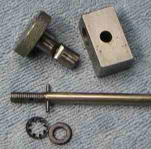 Construction is simple and arbitrary, mostly depending on scrap available. I used a 0.234 (6mm) diameter rod from a line printer to replace the original threaded rod. A cotter was made from 3/8 round (about 3/16 longer than the stop block body) by end drilling for a 10-32 tap, clearance drilling just over half the length, then tapping.
The stop block was pilot drilled to provide the intersecting holes when drilled to size, where the hole for the stop rod was positioned so the block would be about 1/16 from the scale on the drill press. The pilot for the 3/8 hole was placed so the center clearance hole would have about a 50 thou wall in the bottom of the cotter. The cross holes were drilled to size carefully (shaft hole first) because of the interrupted cut part way through. The shaft was put in place and drill shanks were tried in the 3/8 hole to measure the clearance; this shank size was subtracted from 0.375 to find the depth of the cotter. The 3/8 round was side milled with a 15/64 cutter at the center to the appropriate depth for the cotter, then cut in half at the bottom of the cotter with a 0.015 slitting saw.
The knob is a found item which was drilled for a press fit on the head of a 10-32 socket head bolt. I cross drilled the stop rod but if you have an M6x1 nut a longer thread would be another way to lock it in place. With the rod in place and the cotter positioned to match the hole for the rod, run the stop block onto the rod and tighten the knurled knob to lock the block to the rod.
When not in use, the stop block is positioned so the top edge can be used with the scale for depth readout. To use as a depth stop, loosen the knob and lower the drill to the desired depth, push the stop block down against the contact and tighten the knob to lock the cotter. It takes little torque to lock it solidly. Alternatively, to drill to a depth, lower the drill point against the item to be drilled and put a spacer equal to the desired depth between the stop block and its contact point, push the stop down against this spacer and tighten; remove the spacer and the depth is set.
I've seen the cotter used to lock the minilathe tailstock and read about them but this is the first one I've made. Easy to make and it works very well, takes only a fraction of a turn to lock or unlock and is very secure when locked.
Update: I've found that I use the depth stop far more than anticipated when I made this mod -- well worth the effort.
Update 2: I replaced the Harbor Freight drill press with a Rockwell and did the same depth stop mod -- see the top picture on the float lock vise page.
This page was last modified by John Moran, HTML tweaker. If you have a comment on this site or its contents,
click here.