
Float Lock Vise on my Rockwell drill press table (Click to enlarge)
* GadgetBuilder.com * © 2019 by John Moran
Last Modified:
Float Lock Vise on my Rockwell drill press table (Click to enlarge)
I saw a fancy float lock vise at a CTHSM member's shop several years ago. I adapted part of the concept by using a bar clamp with my drill press vise, holding the bar against the drill press column to prevent rotation of the vise should the drill grab; this was done for drills over 3/16" since holding the vise works adequately with small drills.
Recently, MrPete222 presented on YouTube a 10 part series detailing a relatively simple float lock vise build. Ken Stokely provided a very nice drawing of this float lock vise and this drawing is available in the "Show More" below MrPete's Part 10. I watched the complete series, which contains several helpful hints, but ultimately worked from Ken's drawings while incorporating several details suggested by MrPete.
I purchased 2 pieces of 1.5"X1"X4.75" from a local machine shop and a foot of 1/2" 13 TPI allthread from the hardware store, total material cost was $9 and the spray can of John Deere Yellow was another $9 at Tractor Supply. All other material came from scrap.
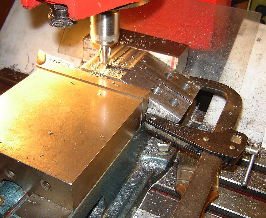 The jaw material was squared up, sized, and drilled following MrPete's directions. I drilled a hole in my bandsaw's table and tapped it 1/4-20 so I could clamp the jaws at an angle -- sawing is much faster than milling. About 1/8" was left to clean up by milling, picture at right (Click to enlarge). Note that I use paper between the work pieces and between the mill's vise and the work - this to ensure the work doesn't slip while being milled. The clamp shown is a hint from MrPete to simplify keeping the work pieces together while aligning the scribe mark to a parallel laid flat on the mill vise's jaw.
 This project divides into two major sections: the vise and the locking mechanism, where the vise is the major part of the work. At right, are the major parts of the vise just placed together, the pins that hold things in place are not included yet. The peculiar spiral pattern on the 1/2" bar wasn't there originally but showed up after the vise jaw made a few passes along the bar - probably something caused during its manufacture, hard to say what it was used for originally since it came from the scrap pile.
As usual, I deviated from the plans slightly, mainly in the locking mechanism. Rather than building a table clamp I found some scrap that had an appropriate size "U" and used that for the table clamp. An eye bolt with 1/4-24 thread was used to lock the clamp to the table; this can be tightened by putting the chuck key through the bolt's eye. A couple 8-32 socket head screws set the distance the clamp extends over the table; the body of these screws is ground flat with the top surface of the table clamp per the directions.
The major deviation from the plans occurred in the lock mechanism. The plans called for two pieces of stock separated with a 1/32" shim. A hole was then drilled centered on this shim, forming a semi-circle in each of the two pieces of stock. Instead, I used one larger piece of stock and drilled and reamed a 1/2" hole slightly above the position needed to cause the vise to contact the table when locked. A 3/8" hole was drilled perpendicular to the 1/2" hole, clearing that hole by about 50 thou. Then, a slitting saw was used to cut along the middle of the 1/2" hole, producing the two semi-circles used to clamp the bar. My 1/32" thick slitting saw couldn't quite reach as far as needed so the last tenth of an inch was completed with a hack saw, leaving a hinge about 40 thou wide. This hinge is the pivot point for the top of the clamp. The top of the clamp only needs to move a thou or so to solidly lock the bar. Unlike the original design where the side away from the bar needs to move 30 thou, this hinge doesn't allow that side to move at all so the top of the clamp remains parallel to the base of the clamp and to the base of the locking screw.
 Of course there's a down side to this one piece clamp design: the clamp can't easily be removed from the vise bar; the piece that connects the bar to the threaded rod must be removed to remove the locking clamp. So, I changed the method of retaining that piece from a roll pin to a 4-40 set screw. There is another caution to this design: don't activate the clamp unless the bar is in place else the clamp will need to be pried open with a screwdriver to get the bar in (don't ask how I found this out). At right are all the parts for the float lock vise other than the pins that hold the parts together. I wasn't enthused about using roll pins to hold things together so I used pieces of 1/8" rod with a fine straight knurl added to one end - easy to tap into place and easy to remove with a pin punch. I made washers from the same 5/8" material used for the handles so the washers are not noticeable when the unit is assembled.
MrPete warned that the clamp could lift the vise clear of the table and that it should in fact hold the vise against the table to help hold the vise in place. I deliberately ensured that the clamp would lift the vise off the table with the idea that I could then "tune" the height by milling a bit off the bottom of the clamp until the vise touched the table evenly on both sides of the fixed jaw. The even-ness of this contact was judged by pulling a narrow strip of paper from under each side of the fixed jaw, adjusting the clamp thickness 10 thou or less between trials. It took several tweaks with the mill to get it right, then the near side of the clamp was fiddled on the belt sander to add a slight angle, about 2 thou was removed on that side. Best I can tell, table friction doesn't add much to stability so it's hard to say if all this fiddling was worth the effort but the vise does make solid contact with the table.
The handle used to open and close the vise took up a whole video by MrPete. This should have alerted me to the fact that this would be an interesting part to make. In fact, it was fairly easy to machine (using the ball cutter to round the ends) although I got the slot on the wrong part (oops) that doesn't affect functionality. The challenge came in bending the handle 90 degrees. I was surprised how much heat was needed and how hard I had to hammer on this to bend it; apparently the handle got a little soft too because the 3 grooves machined in had to be cleaned up afterward with a file. Also, when the handle is approaching a 90 degree bend then the hammer force is parallel to the vise jaws holding the handle. I used thin aluminum strips on the vise jaws to protect the handle and the handle started to move in the vise toward the end of the bending process from all the hammering.
In use it doesn't take much of a twist on the locking screw to lock the vise in place. I commonly go through several increasingly larger drills to get a hole to the desired size. When hand holding the vise you must fumble around each time you change drills to get the hole centered under the drill; with this vise the hole remains centered, so it's a labor saving device!
If you have a comment on this site or its contents,
click here scroll down and click again.