A slide ringing table allows one to spin a slide about its center point while applying paint, shellac, etc. in rings using a small brush. Slide ringing tables are often used to help produce and/or finish microscope slides when round cover slips are used. Although they were more common years ago, slide ringers can still be purchased however they tend to be expensive. This document describes home construction of a servicable slide ringing table from discarded or "found" parts.
A slide ringer can be used for several things. If you have a diatom test slide from Klaus Kemp you will note a small "finder ring" around the 8 diatoms to help locate them quickly. In addition, the edge of the round coverslip is sealed to the slide very neatly, again using a ringer.
On coverslips that I ring, I let the dark colored edge sealant dry, then add a thin white ring on top to allow identifying the top of the slide while not wearing glasses.
Another use is making support rings to avoid crushing a specimen when applying the cover slip. This was my original motivation since I wanted to make whole mounts of deer ticks without mashing them in the process. I tried using punched paper (lots of stray fibers) and punched tape (melted by xylene in the mountant) with poor results; shellac rings are easy to make and work very well.
Another ringer use is making darkfield stops on round plastic cutouts; just center the plastic piece, then use paint to make a perfectly round stop.
Theoretically, it is also possible to make a round coverslip from a square one on a ringer using a diamond scribe. I don't know how to secure the coverslip while doing this, perhaps tape at the corners. I purchased some round coverslips so this isn't something I plan to try in the near future...
Here is an article on uses for a slide ringer and a second article on making a condenser phase ring using a slide ringer. If you know of any other articles on slide ringers, please advise me so they can be included here. Corrington's book, "Working with the Microscope" contains several helpful pages on use of a slide ringer in Chapter 6, Cell Mounts.
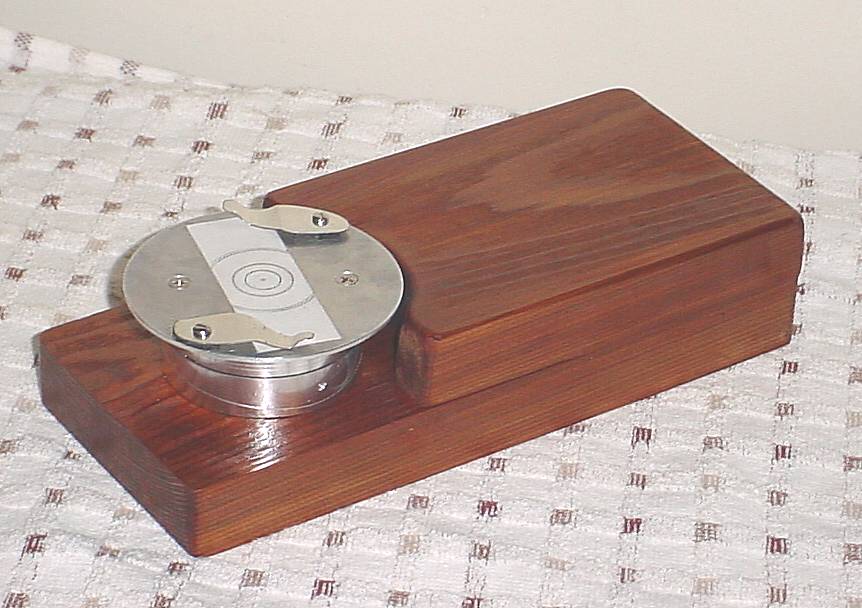
The ringing table described here is built using parts from a discarded VCR plus some additional "found" items like scrap wood, a hinge, and some wood screws. Although my out of pocket cost was nil it did take several hours to construct the unit so it's a labor of love rather than a money saver. Much of my time was expended constructing internal storage for the commonly used ringing materials, a nice touch but labor intensive.
This project requires the typical tools collected by a homeowner plus a few odd items. Power tools for wood working are an asset but not necessary; in particular, a drill press (aka pillar drill)[a hand drill will work], a router, a grinder (and/or a Dremel Tool), and an electric sander are helpful. One oddball tool which isn't common: a 2 1/8" hole saw is the simplest way to make the large hole for mounting the rotating table. Also useful are 6-32 and 4-40 taps and a tap wrench. A small allen wrench (0.057 across the flats, 1.5mm??) is needed -- the size may be different on your VCR...
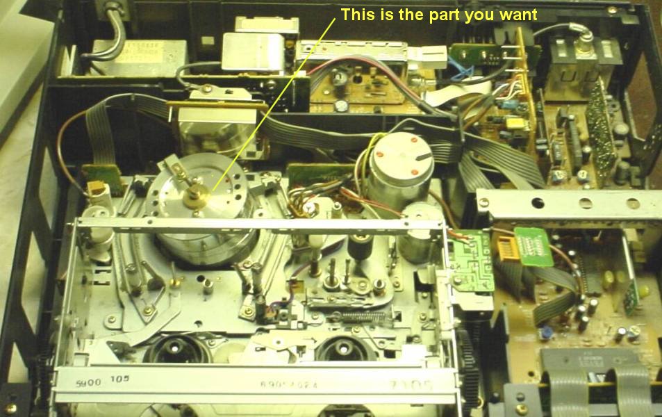
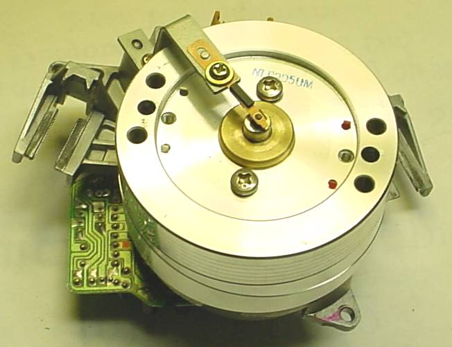
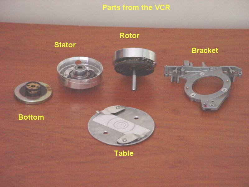
Remove the cover from the VCR to gain access to the innards . It took 3 minutes to remove the needed part. Here is another picture of the major component you'll need from the VCR (this one from a 2nd VCR). It is fairly easy to recognize since the rotor is 2.5" (actually, 6cm) in diameter and it is located almost centrally behind the opening where the tape is inserted. It is generally supported on a bracket secured by 3 screws; unplug or cut the wires involved and remove the screws to extract the complete assembly. (In the second picture, all the wiring and extraneous parts have been removed.) Give the rotor a spin before removing it -- it should continue for at least 30 seconds and be noiseless else you need to find another unit. (After completion, I found my table will spin for 1 minute and 22 seconds when given a vigorous flip.)
To remove the bracket from the motor, remove the lower section of the motor (below the bracket) using an allen wrench to loosen the set screw. Remove the screws which secure the stator to the bracket and the complete motor and head assembly will lift off the bracket. Remove the cap (if any) from the top of the shaft with pliers (it just pulls off).
The rotor can be separated from the stator by simply pulling upward once the lower section has been removed. Remove all the wiring as well as the heads from the rotor. I used pliers on the screws securing the heads because I didn't have the spline wrench required -- lots of freedom in how things are done because the delicate parts aren't needed for our purposes. Do be careful not to drop the motor parts since the ball bearings are precise and easily damaged. Remove the set screws from the rotor (visible from the top, may not be in all units) -- they are removed to allow drilling the holes out. Here is a picture of the resulting parts collection, including the table I fabricated and the VCR bracket which was eventually discarded.
In addition to the spinner there may be a number of useful items in the VCR. I pulled the shiny metal covers from the electronics assemblies and cut one up to make the slide clips (some of this metal was not suitable but one cover had good springiness). This VCR (found at the local recycling center) also had nice rubber feet which were easily removed for re-use.
Check the VCR rotor to see whether the steel shaft and/or the two screw heads protrude above the rim. If so you can either grind things down below the rim of the rotor (as I did) or use table material which is thick enough to allow a clearance hole(s) to be made in the bottom of the table without affecting the top of the table. It is essential that the table contact the rim of the rotor to ensure that the table doesn't wobble vertically.
The rotor had a number of holes so I selected a pair of small holes which were on opposite sides and happened to be on a 2" diameter. I opened these holes to accept a 6-32 tap and then tapped them -- tapping the soft aluminum was slow since the tap had to be repeatedly backed out to clean the swarf from the flutes. Each rotor can present a different situation so you may need to mark and drill holes to attach the table without reference to pre-existing holes.
You'll need some flat sheet material to make the table which is screwed to the top of the rotor. I had a piece of 0.064 aluminum large enough for the 3.5" circle needed. Other possibilities are scrap formica, 1/8" ply from a hobby shop, or the top or bottom of the VCR case (unless it is steel which is hard to work).
A more exotic table could be made using a platter from a discarded computer hard disk: I found one which was 3.75" diameter with a 1" central hole, 50 mil aluminum. You'd need to add a 1" by 3" piece of metal to cover the central hole and serve as a slide locator but the copper sheen would certainly be attractive. Dismantling a hard disk is a bit time consuming, however...
Mark a circle on the bottom of the table material at 3 + 9/16 or so diameter (a little larger than the 3.5" target size to allow for mis-centering and truing after the mounting holes are drilled). Add a circle at the radius of the holes to be used to mount the table to the rotor. Mark the position of the mounting holes by scribing a diameter which passes precisely through the center point and intersects the mounting circle at two points. Cut the circumference of the 3 + 9/16 circle with a saw or metal nibbler, depending on the material and your tools. Drill the mounting clearance holes and then countersink these holes so the 6-32 flat head mounting screws are flush with the table (not absolutely necessary but it looks nice and the countersunk screws locate the table very accurately and securely which is helpful when truing the table radius).
Mount the table on the rotor, place the rotor shaft into the stator and spin the table. Mark a line at the outside of the table with a pen, then remove the rotor and file the circumference to make the table radius approximately true. Re-spin/mark/file to get it very close. Then, put a single layer of masking tape on the rotor shaft, chuck the shaft in the drill press, spin it up, and press a file lightly on the table rim, using the drill press as a crude lathe -- this is slow but it does work.
Construction of the slide clips is obvious. I used 4-40 screws tapped into the outer part of the table with small pieces of inner tube to provide spacing about equal to a slide thickness as well as some springiness.
Use rubber cement to glue a 1x3 piece of a 3x5 card to the table, this to serve as a slide locator guide. To accurately gauge the center, first draw a 1" or slightly larger circle on the table by spinning it and using a pen (the table is useful already!). Once the card is in place, mark concentric circles on it as desired plus mark the center of the table. This card can be removed and replaced, with new circles re-drawn as desired, or circles can be embossed into the table itself using a tungsten scribe. Permanent scribing should be delayed until the table is mounted since the wood frame will be helpful in this process.
The stator could be mounted several ways. I chose to simply use wood screws through the bottom of the stator, angled outward to engage the wood frame. The motor parts in the stator were removed: the winding was pulled out, then the flat ferrite disk was gently chipped out using a cold chisel(Hammer Mechanics take note!). The ferrite is brittle and easily removed except at the glued points. All that is necessary is to gain access to the area near the holes for the locating pins. I re-drilled these two holes at about 45 degrees outward using a clearance drill for the wood screws, then counter sunk these holes to allow the screw heads into the aluminum enough so that they clear the rotor when it is put in place.
As usual, the wood mount for the ringing table was made from available scraps of wood. The design of the wooden mount is arbitrary; I happened to have a piece of 1" thick cedar left from a home repair -- this wasn't the best choice of wood since I found the cedar tended to splinter and chip easily; a hard wood like maple or birch would likely have worked better. The cedar was available and is attractive when varnished.
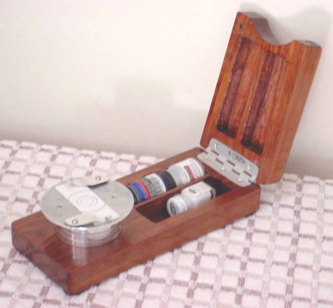
The base is 4x1x9 with a 2 1/8 inch hole 2 inches from one end. The hand rest is 4x1x5.65; the hand rest is hinged to the base and the area between these blocks is hollowed out to provide storage for small jars of paint, slide covers and tools. Because the hand rest is only 1 inch thick, it is slightly lower than the table -- some ringers have a rest which is higher than the table and extends partially over the table so the brush may be steadied against the end of the hand rest (if other material had been available I would probably have made an overhanging rest). (To save considerable time and effort, simply screw or glue the hand rest to the base without routing out internal storage space.)
I asked for help in applying the Slide ringer in the Yahoo Microscope forum. Two of the responses are reproduced below.
The aqueous mountants, sometimes called gum, and dry mounts require sealing. Ringing should be delayed on slides that use a mountant containing xylene or toluene (resin mountants). The solvent (xylene) in resin mounts needs to evaporate in order for the mountant to harden. This may take a month or so, after which you could use any paint that would adhere to glass for appearance and to stop further evaporation of the solvent (which could eventually shear the coverslip).
The aqueous mountants require sealing, after initially hardening, because they can over-dry or absorb moisture from the air and re-soften. Since these mountants contain water, you should seal them with a solvent based paint, ie. gold size, enamel, asphalt. After sealing a pigment paint like acrylic can be used for appearance.
I've found a reference that recommends a #00 artist sable brush. I have some of that size and they measure about 3/64 inch diameter. One idea is to partially stiffen the upper part of the brush with cement and reshape the point by cutting it into a chisel shape. Try to flow the sealant off the brush. Tim Henry
An excellent source of advice is the collection of notes by Eric Marson of NBS in the UK. (I think Brunel Microscopes also sell his book). He recommends moistening the brush with the neat solvent of the ringing cement, and drawing the brush to a point on the edge of the pot or bottle, before dipping it in the cement itself. The technique works for me.
I made a ringing table from an old 4.5" gear wheel and bearing, some scrap wood and brass strip . The key point is to have a really heavy table so that it keeps spinning steadily for at least a minute. Then you have time to get relaxed and accurately lined-up with your brush. Graham Bate