
* GadgetBuilder.com * © 2012 by John Moran
Last Modified:
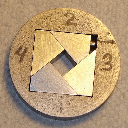
Tap Chuck, click to enlarge
I saw this tap chuck at Mike Cox's site and was intrigued by the operating mechanism: one jaw is screw driven and the other jaws are activated by the constraints imposed by the holder and the other jaws geometry. I wondered whether the friction between the moving parts would lead to balky operation. Once completed I was surprised how smoothly and easily it operates. The design is found in the Workshop Practice #26 but as usual I took some liberties with the original design.
 The jaws are about 3/8" thick and the long edge of each triangle is exactly 1" long, making the short edges 0.707". I started by cutting a 1/2" thick slice from the end of some 1.25" square scrap. This was milled on both sides to get it to 3/8" thick and then lapped on carbide paper to remove the cutter marks. It was scribed corner to corner both ways on one side and then cut along these lines with a slitting saw to separate the 4 jaws.
These roughly shaped jaws were then filed and lapped on carbide paper to get the right angle to be 90 degrees as judged by holding against a square with a bright light behind it. This was the beginning of the fussing - it took a while to get a good fit on all the jaws. The lapping left the short sides of the jaws smooth, i.e. the cutter marks were removed leaving a smooth surface.
 Next I made a simple jig from 1/4" thick aluminum (picture at right) to hold these chuck jaws so the long side of the triangle was parallel to the Mill's table and somewhat above my vice's jaws. The roughly shaped chuck jaws were slightly different sizes so I took the largest, put it in the jig and secured it in the vise. Then I milled the least amount which cut the full length of the jaw's long side. I then compared the lengths of the short sides of this chuck jaw and filed the bottom of the jig to tweak the angle the jaw was held, making the jig hold the jaw closer to position needed so the short sides were the same length. This was repeated a couple times, taking just a few thou with each pass until the jig held the jaw properly.
Each of the chuck jaws was then milled in this jig so the short sides were about 0.708+. This took more fussing because each milling pass left a burr on the ends of the triangle and these burrs had to be carefully removed in order to measure the length of the short sides. Once the short sides were within a thou or so of the desired length then the long side of the triangle was lapped on carbide paper, pressing harder on the side where the short side is longest, until both short sides were 0.707". This lapping also removed the cutter marks from the long side of each of the jaws. Once all the jaws were finished this way they were arranged in a square with the long sides out and a piece of 0.032 stainless safety wire was wrapped around the outside to hold them with all the points meeting in the center; the height and width were verified to be 1" +/- 0.001" using a caliper.
The holder for the jaws was turned from a cast iron barbell. Thickness was made 4 thou more than the jaw width to provide clearance so the jaws could move easily. The hole in the center was drilled 1/4" then milled approximately square but 1/16" inside the desired 1" square size using a 1/2" end mill. Then it was milled to 1.000" square using a 1/4" end mill; the DRO earned its keep here - the hole was within a thou. The rounded interior corners were squared up with a triangular file. The corners were filed just slightly more than necessary to ensure they didn't cause binding - the corners don't provide guidance for the jaws so this doesn't affect operation negatively. The apparent colors of the jaws in the picture is just the way the light reflects from the marks left by lapping.
 The drive screw I chose is a 6-32 socket head which needs a 3/32" hex (some 6-32's use a larger drive). This screws length was carefully adjusted so it just fit in the 1" square hole - the head touches one side and the other end touches the other side with perhaps a thou clearance.
The holder and jaws were gripped in the mill vise with a piece of oiled paper on either side of these jaws to keep them centered in the jaw jolder. The holder was held at the side of the vise so one edge of the 1" square hole could be set exactly vertical, the holder+jaws was drilled 1/8" in from the edge of the 1" hole with a #34 drill; depth drilled was 1" ensuring it didn't go all the way through the #2 jaw see picture. The hole through the #2 jaw was then drilled through on the drill press and enlarged for tapping 6-32 and tapped.
The drive screw I chose is a 6-32 socket head which needs a 3/32" hex (some 6-32's use a larger drive). This screws length was carefully adjusted so it just fit in the 1" square hole - the head touches one side and the other end touches the other side with perhaps a thou clearance.
The holder and jaws were gripped in the mill vise with a piece of oiled paper on either side of these jaws to keep them centered in the jaw jolder. The holder was held at the side of the vise so one edge of the 1" square hole could be set exactly vertical, the holder+jaws was drilled 1/8" in from the edge of the 1" hole with a #34 drill; depth drilled was 1" ensuring it didn't go all the way through the #2 jaw see picture. The hole through the #2 jaw was then drilled through on the drill press and enlarged for tapping 6-32 and tapped.
The long side of each jaw needs to be shortened to 0.75"; as seen in the picture I shortened the #2 jaw to 0.65" to make room for the head of the drive screw. Drilling through the holder into the #2 jaw also left a hole in the #3 jaw; this area needs to be slotted to clear the head of the drive screw. In addition, the #4 jaw needs to be slotted to clear the drive screw when the jaws are fully opened.
 The mounting base was turned to have a 3/8" spigot so it could be held in the tailstock chuck. A 1/8" hole was drilled and reamed in the center to aid in centering the jaws on the base. The holder for the jaws was clearance drilled for the 8-32 button head screws used to secure the jaw holder to the base. A 1/8" pin was inserted in the center hole in the base, the holder was placed on the base and the jaws were closed to grip this pin. One hole was drilled through one of the mounting holes into the base, tapped, and an 8-32 screw used to secure the holder to the base (along with the center pin). The other 3 holes were then D/T 8-32. A scrap of Lexan from the front of a CD player was mounted on the face of the holder; the chuck was mounted in the lathe and the OD of the Lexan was turned down to match the outer diameter of the base and holder which were also trued to match at the same time. The 1/8" center pin and jaws were removed and the center hole in the Lexan was drilled and bored to clear the maximum jaw opening.
I used Lexan as the cover so the mechanism could be seen - I was mostly intrigued by the mechanism, not sure I really need a tap chuck but it was a fun project. The mechanism moves very smoothly and easily but jaw #3 doesn't contact as tightly as the other jaws because the sum of the clearances affects it the most.
If you have a comment on this site or its contents,
click here scroll down and click again.