* GadgetBuilder.com *
Last Modified:
Click to Enlarge
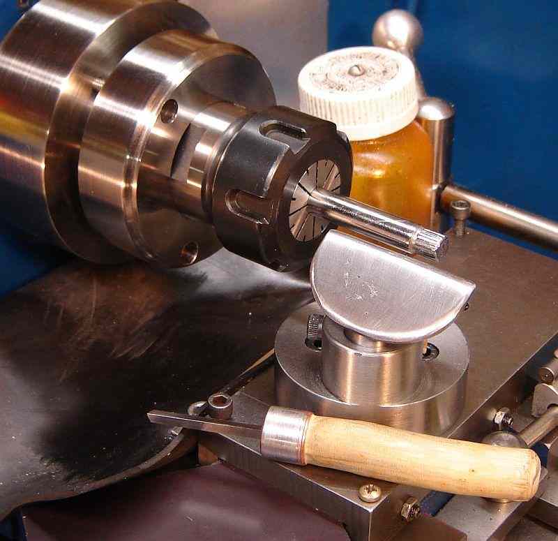
I built a graver rest for the graver demonstration and tutorial at the January 2009 meeting of the CTHSM group held at my shop. WR Smith's information, found on the Sherline site provided the basis for my version. Gravers aren't often used with chucks lest the user or the graver get tangled in a chuck jaw so we used the collet chuck I cobbled up from an ER-32 tool holder.
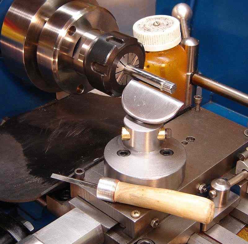
Gravers are generally used for small diameter work so clearance over the cross slide and base of the graver rest shouldn't be a problem but I made my rest eccentric anyway so that I could get additional clearance should it be necessary. Plus, it made it easier to get at the bolts to secure the rest to the compound's bevel.
The base is 2.4" diameter steel 1.4" high, turned down to 0.675" high around the pedestal which holds the rest. The eccentric pedestal is 1.2" diameter, offset so that it touches the outside diameter and the center of the base. In turn, the 0.625" hole for the shaft is offset so it is 1/8" from the outside diameter. This was done by offsetting once to turn the eccentric with a further offset to bore the hole; both operations were done in the Rockwell's 4 jaw chuck. The 1.4" overall height for the base was chosen to place the top of the rest about 1/4" below the centerline with the rest at it's lowest position.
The rest is 1/8" thick, 2" wide and 1.1" front to back, with the rear corners rounded arbitrarily. The 0.625" shaft was cut at 30° such that the rear of the rest will touch the base when the shaft is at it's lowest position. A hole was drilled in the rest so it would be centered on the shaft when the rear of the rest was even with the shaft; the sides of this hole were angled with a countersink. A small hole was drilled through the rest and into the shaft adjacent to the large hole for a pin to hold the plate aligned while setting up for welding. The shaft was held in a vise with the rest laying flat on the top of the vise and a pin in the small alignment hole. The MIG welder set for 1/8" material made short work of filling the hole and securing the rest to the shaft. Of course, it took a while to file the bump it left down... The forward edge of the rest was rounded slightly to better support the graver. The rest can be raised and rotated, where the shank is then locked in position with a split cotter made of brass and activated by a 10-32 socket head bolt. As usual with a split cotter, it locks positively with little force so I may eventually make a small knurled head for this bolt.
A graver was made by turning a handle from a small tree branch, adding a piece of 1/2" pipe as a ferrule, and then installing a 1/8" cobalt lathe bit per WR Smith's directions on the Sherline site. The desired angle on the tip happens to be the same as used for the tangential tool so this graver was quickly and easily sharpened using the tangential grinding fixture. Eventually I made another graver from 1/8" round HSS; I found it difficult to get a smooth concave surface with the square graver.
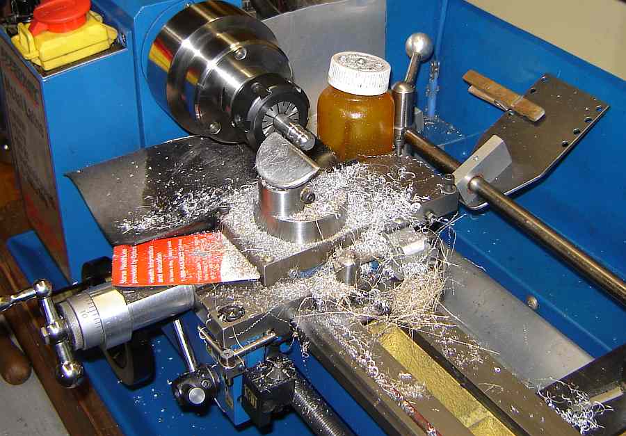 As part of this CTHSM program members brought wooden handles to the meeting (their homework). At the meeting 1/8" HSS bits were installed and then sharpened using the jig for tangential tools. Members honed their gravers and tried the demonstrated graver techniques using their new graver. Each tried the graver on aluminum, brass, and steel to demonstrate the difference in "feel" from these differing materials, generating considerable swarf in the process, as seen here...
The graver rest on the cross slide takes a couple minutes to install or remove. I found that I frequently wanted to use the graver for minor details but the time to swap the rest in and out was an issue for these minor uses. 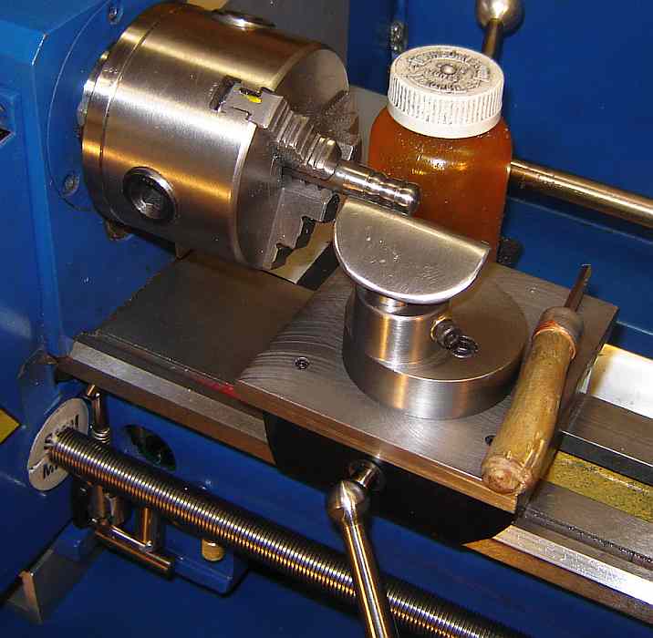 Geo. Thomas built a graver rest that installs with a twist of a handle, as described in his "Model Engineer's Workshop Manual". I adapted his concept to the minilathe by using a camlock plus a locking plate that fits between the ways and is then rotated before locking via the cam. It was built from scrap aluminum plus a bit of 3/8" steel plate, an old bolt, some shaft from a line printer, etc. (the usual junk). A tapered hole was bored in the steel plate and a tapered plug was fitted, similar to the method used to mount the compound. The graver rest bolts to this tapered plug just as it bolted to the cross slide.
In use, the carriage is cranked out of the way, the mount is placed onto the ways, capturing the front "V" and allowing the locking plate to go between the ways. I reach up under the bed and turn the locking plate 90°, slide the rest into position and lock it with the cam handle. The cross position is adjusted by rotating the rest (taking advantage of the eccentric mount) then the rest itself is rotated in the eccentric as needed to address the work. After initial adjustment of the eccentric it seldom needs to be moved so installation and removal is very quick, less than 30 seconds.
I find myself using the graver with a chuck fairly frequently, mostly making minor tweaks to something turned in the chuck - chamfering, cleaning up the edges of a knurl, rounding things for esthetic reasons, etc. This isn't recommended because the chuck jaws could catch the graver or its operator.... For us old geezers this is life in the fast lane.
This page was last modified
by John Moran, XHTML tweaker. If you have a comment on this site or its contents,
click here.