
4/6 Facet Drill Sharpener, Point Splitter Optional
* GadgetBuilder.com * © 2014 by John Moran
Last Modified:
Click Pictures for Details
4/6 Facet Drill Sharpener, Point Splitter Optional

 This page describes shop built drill sharpening jigs,
NOT hand held sharpening on a bench grinder.
This page describes shop built drill sharpening jigs,
NOT hand held sharpening on a bench grinder.


Sharp drill bits are helpful in getting the best from the minilathe as well as the drill press, mill-drill, and even a hand drill. The Pit Bull type inexpensive conical sharpeners can do an acceptable job on twist drills from 1/2" down to about 1/8". Small drills are not handled by this sharpener so another approach is needed. Ian Bradley's HoneDrill fixture can sharpen medium/small size drills, facet larger drills, and hone some other cutters. Derek Brown's four facet drill sharpener is easier to build and quickly sharpens small drills very well; both are described below. As is using the Pit Bull type sharpener for larger drills. Note that few commercial sharpeners handle small drills (under 0.100"). Sharpeners for small drills are expensive so Derek's four facet sharpener is the best option for sharpening small drills in the home shop.
My interest in building a drill sharpening jig arose from reading that four facet drill geometry improves overall drill performance. Four facet geometry: reduces wander at startup, needs less pressure for drilling, generates less heat, and wears more slowly. I had noted that center drills can wander at start of drilling: their short, stiff nature isn't really a solution so much as a way around most of the problem. My original goal was to produce center drills with four facets to reduce wander at startup -- the ability to sharpen all small drills was a fringe benefit which happened to come along with the sharpener for center drills.
My understanding of drill point geometry and drill sharpening improved considerably from reading Mazoff's article and especially from using the HoneDrill fixture. Adjusting and using this fixture is effectively a mini-tutorial on drills and their geometry. Plus, it allows experimenting with relief angles, easily allowing four facet and six facet sharpening of drills, for example. Derek Brown's sharpener is much easier to build and use but doesn't illustrate drill geometry variables as well since they are fixed during construction. Hand powered drill sharpening is practical for very small drills but for drills greater than 1/16" I eventually designed and built a powered 4 facet sharpener (to implement some of Mazoff's notions) which I prefer to all other powered sharpeners I've tried.
Joseph Mazoff's article on drill point geometry suggests conical drill sharpening is easy to do but conical drills don't perform as well as faceted drills and that most drills sold in the US have excessive relief. The pictures are interesting and show some advanced geometries not often found in the typical home shop. More from Mazoff here. However, reduced relief for larger drills can easily be provided by adjusting the inexpensive sharpener differently than suggested in the directions or by adding a primary facet with the HoneDrill. Small drills can be ground at any desired relief angle(s) using the HoneDrill fixture and four facets can easily be produced if the user desires. Derek Brown's four facet sharpener produces fixed relief angles of 10° and 25° although the fixture is easily modified to produce any two selected relief angles - however, once selected they are fixed forever. Reduced relief is helpful in reducing chatter and hogging in, often a problem when using inexpensive drill presses because the minimum speed is higher than desirable for many drilling tasks.
Sharpening drill bits by hand on a bench grinder is often cited as a skill which all "real machinists" should develop (frequently followed by a dissertation on proper technique and wrist motion). After reading the article on drill point geometry my conclusion was that a hand sharpened drill may work but it is unlikely to work properly and the next drill sharpened by hand is unlikely to work the same as the last one. There are simply too many interacting variables that must simultaneously be correct and identical on both flutes for this to be done accurately by eye. Most workers can't accurately hand grind a lathe bit to 7° relief let alone get two conical drill flutes identical with 118° point and 7° relief while ensuring the cutting lips are at 180° and the same length within a thou or two.
My approach to achieving sharp drills evolved as I went along (learning about drill geometry and building sharpeners). Initially, I expected a one-size-fits-all sharpener but found it easier to get good results by using several sharpeners to cover the size range. Present strategy is to use the Brooks on drills over 1/2", the 4/6 facet sharpener on 1/2" to 1/16" drills. For small drills (#42 to #80) the hand powered Four Facet Sharpener does a great job although small drills can be sharpened on the 4/6 facet sharpener.
Building and using the Four Facet and HoneDrill sharpeners along with the Pit Bull provides a practical education in drill sharpening. The HoneDrill in particular is educational and also thought provoking. The combination of the Pit Bull plus Derek Brown's collets is reminiscent of a Champ Sharpener's dual bed. Since building the Brooks cutter grinder I've added a HoneDrill inspired jig to it for sharpening larger drills. Motorized 4 facet grinders are available but expensive (see Christen or Optima) so I recently built a 4/6 facet sharpener with a much different design.
Click to Enlarge
Derek Brown's article describing his Four Facet Sharpener for small drills (#42-#80) appeared in "Model Engineer" for January/February 1994; the article was updated and reprinted in the same magazine in May 2000. A version for drills to 1/4" appeared in "Model Engineer" for August 1996. Derek was kind enough to supply copies of all these articles when I couldn't find construction info on the net. My interest originated from a variant of Derek's unit shown on Alan Marshall's site (disappeared since). This hand powered Four Facet Sharpener works very well for small drills; for those who would like to build one and can't find Derek's articles I have provided enough info here to allow construction. A motorized 4 facet grinder is used for larger drills.
The clever thing about the pin vise for the Four Facet Sharpener is that it is rectangular. This makes it easy to get both sides of a drill aligned the same: simply flip the vise over. The vise works in the HoneDrill fixture too although the nut prevents it from registering properly on the back end; this can be compensated by adjusting the fence but I made a longer version of the pin vise so these nifty collets can be used easily in both fixtures.
The article indicates that slitting the collets is the trickiest part of building the unit so I made the collets first - if I couldn't make the collets there would be no need for the tool block. The collets are made from 5/32 drill rod where 4 collets will accommodate drills from #42 through #80. I used a 5C spin indexer to hold the collet blanks for slitting but since I didn't have a 5/32 collet I used a 3/16 split sleeve to hold the 5/32 blank in a 3/16 5C collet. Confusing to describe but it worked well. I stopped the mill to take this picture of the process. The saw is a Thurston 0.015 thick blade, close to the 0.016 blade specified in the article. The collet blanks are 5/32 drill rod, 1.30 long where the body is drilled out with a #42 drill except the last 3/16 which is drilled to size the collet. The drill sizes specified for this are: 42, 49, 55 and 68 -- I didn't make the smallest collet (yet). The end of the collet blanks are tapered at 15° and a 15° reamer is made from the same drill rod to form the taper in the body of the pin vise. The vise body is 1.5" long by 0.250 by 0.220, drilled out to 3/32 then enlarged to #22 = 0.157 except the last 1/8" which is reamed with the 15° reamer leaving about 1/32" un-reamed; I put the reamer in the lathe chuck at low speed and pushed the vise body onto it by hand, cleaning chips out and checking progress frequently. A 9/16 long brass nut threaded 10-32, also through drilled 3/32" completes the pin vise. I added grooves at the rear of the collets to identify the size. This collet and pin vise work really well, little force is needed to solidly lock a drill in place. The collets expand slightly when slit so they must be removed from the pin vise by pushing them with a small drill.
Machining these tiny collets is fussy work; some details concerning this: I made a split sleeve by end drilling a 12 inch by 3/16" brass rod about 5/8" deep, then adding 4 slots with the 0.015 saw. The rod was run through the 5C collet and extended out the other end of the spin indexer. A drill chuck was clamped on this end and used as a handle to move the split sleeve in and out while inserting and removing collets. Slitting was done by approaching from the side of the collet blank with the saw set to clear the 5C collet by about 1/16". The collet blank extends 1+ inch from the 5C so it is gripped by about 1/4" of its length -- this allows slitting about 15/16" of the collet length. My saw blade is small diameter so the end of the collet conflicts with the saw arbor; this forces completing the slit by rotating 180 and coming in again. When slitting, a curl of metal comes out of the side away from the blade and this occurs inside the collet too. This swarf should be removed in place as best as it can be after each cut else the blade will re-cut this swarf and could jam and break. After cleanout, rotate 180° and complete the remaining part of the slit on the other side, clean swarf again, rotate 90° and make the other slots, cleaning after each cut. On completion, the collet will be full of swarf and have burrs so run the #42 drill in by hand as needed to clean things out. In addition, the exterior of the slots will have a burr along the length which must be removed before the collet will fit into the chuck. It takes about as long to clean and debur a collet after slitting as it does to slit it. The collets need not be hardened.
I made the main tool block from scrap aluminum rather than (1x1.5x2) steel as called for in the article (if it wears rapidly I'll make one from steel or HDPE). The article recommends angles of 10° and 25° for the sides; these angles set the relief angles for the facets. Opinions vary on appropriate relief angles, where other sources recommend 6° and 20° so I split the difference and used 8° and 20°. I squared up the stock and scribed lines showing the angles on the end, then used these lines and a parallel laid on the top of the vise to align the part to the vise top and milled the angles into the block. The vise was rotated 59° so the slots for the pin vise could be milled into the angled sides. Each side in turn was set even with the top of the vise and a 1/4" wide by 0.220 deep slot milled so it went through the geometric center of the side - this picture shows a slot being cut. The slot at 59° is appropriate for a 118° drill, the point angle found on most twist drills. To handle a variety of angles the HoneDrill fixture is more appropriate; the Four Facet Sharpener is simpler and faster to use but less flexible in the tasks it can handle. This shows the end and side views; note the slot for the pin vise goes from upper right to lower left - this is true for both slots in a block.
To complete the unit I added black Delrin side plates using 6-32x1/2 flathead screws. The pin vise should be a shake free fit in the slots so make any minor adjustments needed to achieve this. The vise is rectangular to ensure it only fits in the correct orientations; I left the vise square until the side plates were added, then trimmed the vise with the fly cutter and made final adjustments on the bench sander. Chamfer the corners of the vise so they don't interfere with the fitting process.
The plans call for the block to run on rails using a diamond plate for sharpening. Instead, I used sealed ball bearings (salvaged from discarded VCR's) as wheels with 6-32x1/2 button head screws as axles. I use #600 carbide paper laid on a granite block for sharpening, where the wheels hold the sharpener body about 1/16" from the paper. The nose of the pin vise is fettled by placing a small piece of cereal box cardboard on the bottom of the tool block for protection, then filing the tip of the vise in place to within 1/32 of the hole -- do this for all possible orientations/positions.
This sharpener is much simpler to use than the HoneDrill and does a fine job sharpening small drills. It takes some experience to judge how many strokes and what stroke length to use vs the condition of the drill. 600 grit carbide paper cuts rapidly, at least when its new: about 6 strokes 4" long is enough to put a 20° (secondary) facet on a #50 drill and 1 or 2 much shorter strokes adds the primary facet. If a drill is damaged or the chisel is off-center and must be corrected then it would take longer than the 2 minutes it takes for a drill which is only dull. It can take longer to put the drill in the collet and align the flutes vertically than it does to sharpen it (but see the alignment gadget below). Centering the chisel is a judgment call where a couple strokes on the shorter side generally does the trick. Re-sharpening a four faceted drill is nearly instant if the drill is only dull - one or two strokes on each facet.
User Note: The article specifies a diamond plate for sharpening and I found part of the reason: grit from stones or carbide paper sticks to the end of the drill bit and can drop off inside the slot which holds the pin vise, making it difficult to re-insert the vise. My solution is to pick the block up and wipe the drill point with a paper towel before withdrawing the pin vise. I tried using this fixture on an oilstone before I figured this out - the oilstone made the problem obvious although it works well when reworking damaged drills needing more than simple sharpening. To clean the slots push a wad of paper towel through; as with most grinder fixtures, never clean with liquid or apply oil because grinding dust will stick to it and cause trouble.
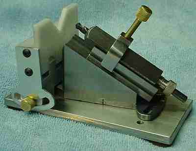
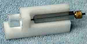 An optical aid to accurately align the flutes vertically is helpful for the tiny drills sharpened in this fixture. The magnifier in this fixture incorporates a line to help judge when the flutes are vertical. This is calibrated by rotating the (friction fit) Lucite lens to align the fiducial line with the side of the rectangular pin vise. The lens design is similar to the optical center punch lens but shorter; the outside surface is spherical while the side toward the drill is flat and has the line -- the focus is about 1/8" from the lens, magnification is about 4. Magnification and distortion increase as the drill is moved away from the lens. The pin vise is held into the corner of the fixture to center the drill in the magnifier.
To keep track of the tiny collets I drilled storage holes in the top of the main block. Friction holds the collets in these holes and the ID rings allow picking the correct one.
I expect that if the main tool block were made 1/2" longer it would accommodate a second slot for the 1/2" pin vise used for drills up to 1/4". Alternatively, 1/2" by 0.475 slots could be made in a slightly larger main block and the small pin vise described above could be made from 1/2" stock instead of 1/4" stock; this would allow this pin vise and the larger pin vise described below to fit the same main block. Unfortunately, I thought of both of these approaches after I built the small block so I'll use the 1/2" pin vise with the HoneDrill instead.
Small drills can be tricky to use because they break easily if too much axial force is applied; a Sensitive Drill attachment can be helpful because it makes it easier to peck drill and easier to judge the applied force.
Click to Enlarge

Ian Bradley's HoneDrill fixture (Model Engineer, Nov. 1961) looked to be flexible enough to allow a little experimenting with drill geometry and seemed easy to build. In use the bit's lip is held vertical by the triangular block and this block is then pivoted about the lip to set the relief angle. The fence can pivot to accommodate slight differences in point angle (118 is standard). While conceptually simple, it illustrates drill geometry and how drills work very clearly. I eventually built what amounts to a motorized HoneDrill to handle larger drills.
I purchased the raw material that I didn't have on hand at a local machine shop for $2 and away I went. 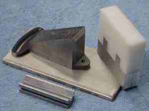 It turns out that, as usual, I didn't estimate the work involved very well. Ian Bradley suggested that the triangular block could be shaped by hand with a file but that the top surface should be machined to obtain a good fit with the V block. I assumed that my milling machine would make the job much easier but it turned out not to be as easy as that. With a file you just work away at any desired angle to shape a part but with a mill it takes another setup for each facet on the part and there are a LOT of facets on the triangular main block and on the parts that make up the fence. Even the little "V" block needed several setups; an angle vise would simplify the setups considerably.
The clamp for the V block was a challenge. I marked it out, milled the inside to the lines (a coordination exercise on the mill handles), then used a Woodruff cutter to finish the feet that engage the slots in the V block. The clamp's top was milled at 45° on each side and then I cheated and used a file to complete it.
The movable part of my fence is HMWP, a plastic nearly as slippery and abrasion resistant as Teflon - it remains to be seen how well it holds up in practice with an abrasive stone rubbing on it; so far it seems OK.
I made a few minor changes. I used only two screws to secure the quadrant to the fence and one of the screws holds the hinge pin. Rather than Allen screws I used flathead screws to secure the fence and main block to the base. The drawing calls for a single bolt in the center to lock the main quadrant but the picture shows two holes; I followed the picture. All of the adjusting screws were turned from brass and knurled. As noted, the movable part of the fence is from HMWP, where the article suggested Tufnol or hardened steel. The fixed part of the fence is aluminum. (I believe there is an error in the drawing in that the quadrant for the fence doesn't fit properly if built per the drawing.) The base is "mystery metal" from the dump; it is a type of stainless that is apparently a close relative of Kryptonite - it took 40 minutes in the bandsaw for one cut 1/4 inch thick by 5 inches long!
If I were to build it again I would make the bottom quadrant long enough to go the length and include the hole for the pivot bolt, then bolt the main block (59° angle), shortened slightly, to it - seems like it would be easier to machine that way. The quadrant for the fence should be on the right, at least for right handed users (I changed it since taking the pictures). It would be useful if this quadrant allowed more inclination away from the main block (an easy mod); this would make it easier to hone the end teeth on slot drills with a narrow India stone. Also, the 59° block could be made from HMWP/HDPE much more easily than steel and based on how well the fence has held up this should work out well.
To simplify setup I made punch marks on the base at 0° and +/- 10° and +/- 20° of relief setpoint, then filed an alignment mark on the rear of the main quadrant, as seen in the pictures.
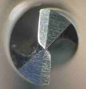
The first drill I sharpened was the #2 center drill shown in the picture at the top of this page. This drill was fairly new so it was quick and easy to four facet it. It now starts without wander but drilling pressure is only slightly reduced.
 I used the HoneDrill to sharpen a very worn split point "F" drill using four facets - not commonly done but it seemed like an interesting thing to try. The result is different looking, as seen in the picture. This was done with a carbide stone. I tried an aluminum oxide stone but it quickly became grooved. I will also try carbide paper glued to a wood backing - I expect fine carbide paper will produce a better surface finish on drills. It took 20 minutes to hand sharpen this relatively large and badly worn drill - it would likely be better to sharpen drills larger than 1/8" with the Pit Bull sharpener and then add a primary facet with reduced relief since this should be quick and easy.
As an experiment I used the HoneDrill to add "Secondary Point Angles" as shown in Figure 4 of the article on drill point geometry. 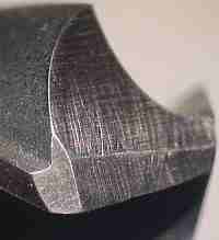 Although it is easily done, it felt like I was ruining the drill because it was such an unusual thing to do. In fact, the section ground away is in the area that I have seen chip on a number of (abused) drills. The 1/4" drill I experimented on cuts steel nicely but it is impossible to evaluate whether all the claimed benefits are actually realized without conducting a controlled experiment. However, it is easy to do and works well so I commonly add SPA facets to drill bits - mostly bits larger than #25 since smaller bits usually cut well even without an SPA.
I had read about adjusting drills for use on brass and plastic but didn't understand how to do it accurately. The HoneDrill does this nicely, just set the relief angle to zero or 1° and add a primary facet; the low angle reduces self-feeding, the cause of grabbing in brass and similar material. I have a set of inexpensive drills from a Homier sale which are dedicated to brass and will be adjusted as needed in this manner. Some material will grab even with a low relief angle; if this happens the rake can be adjusted with a slipstone, making a very narrow facet parallel to the drill axis on the front of the cutting lips. Note that four facet drills cut well in steel but tend to grab in brass because they do cut so well.
The HoneDrill can sharpen things other than twist drills. End mills sometimes chip on the end of a flute and one way to continue using them is to make a small facet at 30° to 45° on the end of the flute (similar to the SPA on drills noted above). The result won't cut sharp 90° corners but apparently lasts considerably longer than an acute corner so this is sometimes done deliberately during sharpening. On the HoneDrill, put the end mill in the V block with the flute vertical, put the fence forward as needed, set the relief angle to 6°-8° and hone to produce a facet. Make identical size facets on the end of all flutes.
"D" bits can be sharpened or even produced in the fixture. Generally, it takes a while to remove much metal by hand with a stone so where possible rough the shape on a bench sander or grinder first then finish to the desired angles in the HoneDrill.
The HoneDrill plans call for a pin vise with locating pins to index small drills for sharpening. After seeing the pin vise and collets for the Four Facet Sharpener and reading Derek Brown's article "Four Facet Sharpening: Extending the Range", Model Engineer August 1996, with scaled up collets I decided to use his approach rather than the one suggested in the HoneDrill plans. Three collets handle the range from about 0.085 through 0.250; 180 degree indexing is inherent in this design.
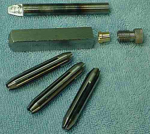 This larger pin vise is analogous to the small pin vise described above except it is made from 1/2" stock 2.5" long. The larger collets are considerably different in design, being slit on both ends so they can collapse onto and accurately position larger drills. These collets have a taper on both ends and the pin vise includes a tapered brass piece on the upper end so both ends collapse simultaneously as the knurled nut is tightened.
Construction techniques are similar to the small vise and collets in many ways. The vise body is drilled 3/8" except the last 3/8" which is drilled 1/4" and reamed with a 15 degree reamer made from 3/8 drill rod as a tapered D bit - same technique as the small collets. The last 1/16" is not reamed, remaining 1/4".
 The 3 collet blanks are 3/8" drill rod 2.188" long, tapered 15 degrees (i.e. compound setpoint is 15 degrees) on each end to 1/4" diameter. The collet blanks are drilled to 1/8", 3/16", and 1/4" respectively. Each collet has 4 slits on each end, where the 1/16" slits are interleaved by rotating the blank by 45° when it is reversed to slit the second end. I held the blanks in the spin indexer where about 1/4" beyond the taper was needed for a good grip. To set the 45° angle a 1/16" thick ruler was inserted through an existing slot to help measure the angle. To allow gripping the slit end of the collet the shank of the drill used previously to bore the collet was inserted just even with the end of the 5C collet holding the blank. The 5C spin indexer works very well in this application, maintaining a sure grip on the collets as they are slit. Slitting to within 1/16" of the 5C was easily done. Deburring was easier and faster on these larger collets than on the smaller collets from the Four Facet Sharpener. Slitting is not a speedy process when I do it; I spent about 1.5 hours per collet just slitting and deburring.
The brass piece is 5/16" long. It is about 5 thou under 3/8" for 3/32" and the remainder is 5/16". The inside is drilled 1/4" and tapered using the reamer previously used to taper the pin vise, the larger diameter toward the large diameter of the brass piece. As with the small collets, brass on steel has low friction and does not rotate the collet as the nut is tightened.
The knurled steel nut is 3/4" long and up to 5/8" in diameter; I made it 0.460 so it is easy to use with the HoneDrill's V block. The plans call for a 7/16-40 thread; I used a 10x1.25 metric tap and die but single pointed most of the nut's thread on the lathe, finishing with the die. The pin vise was threaded with the tap, going only as far as necessary. Run the 3/8" drill in by hand to gently clean up any metal raised by threading or the collets won't enter easily.
The clamp for the HoneDrill would not allow the 1/2" pin vise through initially. I chamfered two diagonal corners slightly to fit; this has the happy effect of only allowing the vise to fit in two orientations, similar to the constraint imposed by the rectangular shape of the pin vise in the Four Facet Sharpener. Here, the effect is the same but is accidental rather than deliberate - some days you get lucky!
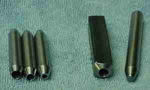
I scribed a fiducial mark across the face of the pin vise between the chamfered corners. This is adequate for aligning by eye the flutes of all bits in the covered range. An optical aid, similar to that built for the Four Facet Sharpener, proved unnecessary so I have an extra Lucite lens awaiting some future project -- a peril of mass production to avoid extra setups.
This pin vise fits into the Pit Bull sharpener as well as the HoneDrill. Chipped or damaged drills can be refigured quickly in the Pit Bull, then transferred to the HoneDrill for faceting. Proper indexing isn't enforced by the Pit Bull holder so you must stay alert to rotate the vise by 180 degrees. Also, when removing considerable material from a drill it may be necessary to adjust the drill bit in the vise to maintain the desired orientation of the flutes to the vise.
The inexpensive Pit Bull type drill sharpener (sold by Craftsman, General and Draper among others) is crudely adapted from a 1913 design by L.A. Van Royen. Van Royen's design was the basis for the Potts jig which was refined somewhat by Duplex in "Model Engineer". This sharpener produces a conical point and is adjustable to handle several common point angles as well as various relief angles. It may be possible to improve the point geometry produced by the inexpensive sharpeners with some relatively simple modifications.
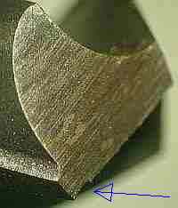 I read on the net (can't recall where) that the grind marks on drills should be perpendicular to the cutting lip. This because grind marks parallel to the cutting lip encourage bending at a grind mark near the lip resulting in fatigue failure which shows up as missing sections of the lip. I had set my Pit Bull up per the pictures in Duplex's article which show the bit touching at 9 o'clock on the wheel; this results in grind marks parallel to the lip. I examined some drills I had sharpened and found rectangular chips in the cutting edge, as shown in the picture. I checked some good quality new drills and found the grind marks were perpendicular to the edge and much finer than the marks on drills I sharpened.
I revised my Pit Bull sharpener setup as shown above. My ancient Baldor has a large nut on the shaft, so large that it prevents the Pit Bull from reaching the wheel if it is mounted so the drill bit would touch at 12 o'clock. So, it is set up to touch at about 10:30 on the 6" wheel. This compromise doesn't yield grind marks perpendicular to the lip but they are now far from parallel and the chipping problem no longer occurs. I am at a loss to explain how Duplex and other sources settled on the 9 o'clock position; my experience is that the results are better if the 9 o'clock position is avoided.
In order to raise the Pit Bull from the 9 o'clock contact I added a wooden pad. This is secured on top of the pad for the Tinker using a socket head bolt with a nut embedded in the bottom of the earlier pad. Similarly, a bolt head is wedged into a hole in the bottom of the new pad so a nut can be used to secure the Pit Bull to the pad -- this is loosened to move the unit as required to accommodate different diameter drills.
Setting up to use this sharpener isn't as obvious as one might expect, given its apparent simplicity. The pivot axis is inclined toward the wheel (see picture above) so its base must be oriented perpendicular to the side of the wheel as shown. The little piece on the front that is moved up to orient the lips perpendicular is not precisely made (and the bit may rotate slightly when advanced) so it is better to use a square to get the lower lip exactly perpendicular. Loosen the bolt that holds the unit to the wood base and position it so the lip orienting piece is one drill diameter from the side of the wheel; this sets the relief where increasing distance reduces relief. Adjust the relief as desired once you've tried a test grind; use the chisel angle to judge actual relief per the article on drill point geometry. Set the part that supports the bottom end of the bit so the bit just touches the (stationary) wheel; use a square to set the bottom lip perpendicular. If you're willing to fuss a bit and are careful to get the lip being sharpened exactly vertical each time you move the bit to advance it or sharpen the other lip then it should do an acceptable job of sharpening - just not very quickly.
The vertical alignment function of the Pit Bull doesn't work well enough to be trusted in my opinion, especially for smaller drills. 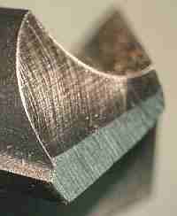 I generally set the lips vertical by eye (or with a square) and results have been acceptable. Grinding a drill, particularly a larger drill, takes a while if it has been chipped or is badly worn. My technique is to repeatedly touch the drill to the wheel briefly, allowing some time for cooling between touches. The contact area is enlarged with each touch until the complete face is ground. Tool steel can tolerate a lot of heat but the lip area is thin, which increases the temperature; better to err on the cool side than to draw the temper.
Using the HoneDrill, a primary facet was added to some drills previously sharpened with the old Pit Bull setup rather than resharpening on the new setup. In some cases it worked out OK, in others there is a bit of a defect remaining. The picture shows a "T" size drill with a small chip at the outside corner; this would likely fail fairly quickly and require sharpening. The obvious solution is to add facets to form "Secondary Point Angles" which removes the chip and should make it less likely to chip again - see the next picture.
Overall, the Pit Bull type sharpener is inexpensive and does a reasonable job sharpening larger drills, 1/4" to 1/2". It works from 1/8" to 1/4" but is shakier in that the alignment is more difficult to do accurately so it is possible to have the lips differ -- this results in wander when drilling deep holes; using the larger collets described above reduces this problem. Using the Pit Bull jig was part of my learning process but has been superseded by the 4/6 facet grinder.
The side of the wheel eventually gets dull and filled with metal particles. A diamond is used to correct this, where I use the Tinker to hold the diamond and move it accurately along the side of the wheel. Very little stone is removed, perhaps 2 thou, taking about 1/2 thou at a time (makes a mess in spite of the small amount removed - cover everything nearby). This doesn't seem like much but it makes a big difference in how the wheel cuts.
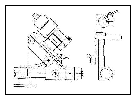
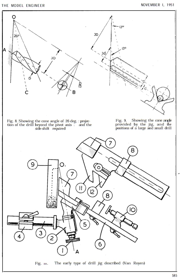 Van Royen's 1913 design (dwg at right) for a conical drill sharpener is available as a kit from Hemingway or via Duplex's construction article in "Model Engineer" beginning November 1951 and repeated beginning November 1963. Click Hemingway's drawing for a picture of what looks to be an original Potts, possibly from the 1920's. A PDF by Prof. Joerg Hugel (Swiss Federal Institute of Technology) containing a mathematical analysis of conical jigs is available on the net; his analysis shows the Potts design produces excellent points while drill points from the Pit Bull design are less than ideal.
An implementation of Oakes design for small drills (includes plans), no inclination to the axis (fixed axis offset since diameter range is small).
The Potts sharpener follows the original Van Royen design closely while the Pit Bull appears to be a simplified version. The Pit Bull axis inclines 6° toward the wheel vs 13° in the Duplex article. The Pit Bull offsets the drill axis a fixed amount from the pivot axis while the Potts varies this offset based on the drill diameter via a caliper built as part of the unit. The Pit Bull handles multiple point angles while the Potts is fixed at 118°. While both designs generate a conical relief, the Potts follows Van Royen's design more closely at the cost of more complexity.
Other conical sharpeners were produced, e.g. the Atlas and Kalamazoo units, but these are no longer in production. I haven't seen the Atlas or Kalamazoo units but the caliper for axis offset used in the Potts isn't apparent so they are likely a different simplification of the Van Royen concept. AFAIK the Potts and Duplex incarnations are the only ones that implement the complete Van Royen concept.
I considered building the Duplex design but decided against it because it handles only 118° point angle. The 4/6 facet sharpener described below is simpler to build and has more capability: 118° and 135° point angles, SPA's and split points.


A member of our CTHSM group found a Delta 1296 at a flea market and loaned it to me for evaluation. This unit was complete and in good condition. Fortunately it was easy to adapt it to my antique Baldor grinder. The very helpful Delta 1296 manual was found at Vintagemachinery.com. The Delta 1296 can sharpen various point angles, e.g. 135, 118, etc.
The Delta unit seems to implement the Van Royen concept accurately except that the offset for drill size is done manually rather than via a built in caliper: the left jaw of the V block is movable via a knob and a scale is provided to set drill diameter. I haven't seen an Atlas unit but the pictures at the link referenced above don't show a movable left jaw, i.e. the Atlas may not implement the Van Royen as faithfully as the Delta.
To sharpen a drill, advance the drill toward the wheel while rocking the drill point past the wheel with the ball handle once for each thou advanced. Continue until that side of the point is completely ground. To rotate the drill to do the other lip you first back the drill away from the wheel exactly one turn (it is marked) using the thimble. Pivot the drill holder upwards and away from the wheel by pushing the thimble down. Loosen the V block, rotate the drill, lightly snug the V block, rotate the drill against the locating pin, tighten the V block, and lift the thimble up until the stop pin hits the block. Then you advance the infeed toward where it was (per the calibration marks) until it is at the same setting as used for the other lip. See the manual for more details. Using any sharpener is the kind of thing you develop a feel for with practice (I only sharpened one drill). The drill I sharpened worked well, about like a new drill, so this seems to be a competent conical point sharpener.
 "Model Engineer" published "A Bench Grinder Attachment for Four Facet Drill Sharpening" by David Lammas in 1986-87. This design uses a drill chuck bored out for a hollow shank so the drill body can pass through, allowing a small drill extension from the chuck for sharpening. Unfortunately, the 3 jaws of a drill chuck don't grip predictably on the flutes of a drill, adding to any inherent eccentricity in the chuck. This may result in the drill being held off center and/or at a small angle, leading to the lips differing slightly after sharpening.

I recently saw an elegant optical gadget for inspecting drill points at a CTHSM member's shop. This precision device has two optics, one to verify point center and another to check point angle. I hadn't seen a method of verifying the point was on center previously so I thought it would be interesting to attempt an imprecise and inexpensive imitation.
I chose a 30x-21mm loupe from eBay to use as the optic. My notion was to use a single optic by hinging it so it could move 90 degrees, thus allowing it to be used for both center check and point angle check. 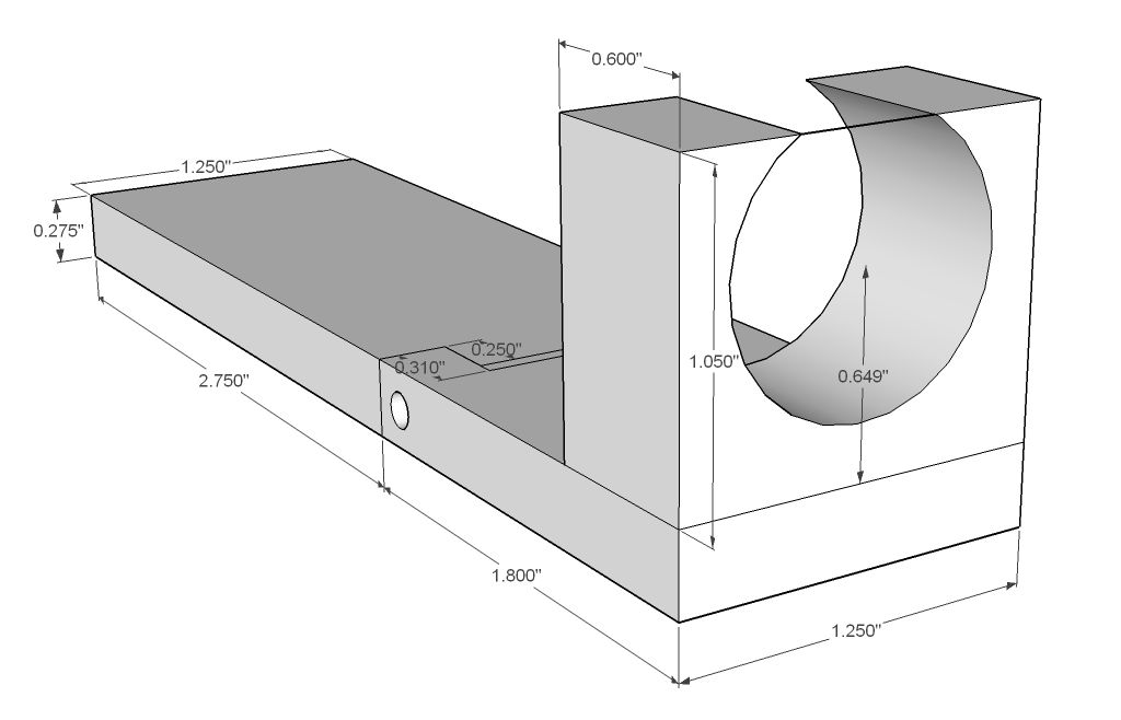 This scheme limits the range of drills handled to 1/8" --> 1/2".
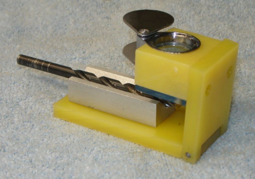
I built a unit from HDPE but Woody, a site visitor, built using a 3D printer and included a couple useful improvements as described here. If you have access to a 3D printer this looks like a nice way to produce an improved version and his site provides the 3D files.
I had some HDPE on hand so it was used for the base and the loupe holder. There are two parts to the base, both are 1.25" wide by 0.265 thick; the sizes and material are arbitrary, based on what was available. The larger part of the base is 3" long, the shorter piece is 1.8" long. The hinge end of the short piece is milled away 0.31", leaving a 0.25" wide section on each side - see sketch at right. The hinge end of the long piece is milled away 0.25" deep and slightly less than 0.25 wide; then it is widened by hand on each side to enable the hinge parts to mate. This should be a tight fit requiring a bit of effort to get the pieces to fit tightly together, ensuring a shake free fit. Place the mated parts in the drill press vise, edge up, and drill a 1/8" hole for the hinge pin. Use a 0.116" drill for a temporary hinge pin as needed while trial fitting the remaining parts. Whittle away the upper area of the hinge parts to allow movement through a right angle - easy removal of the hinge pin is helpful here.
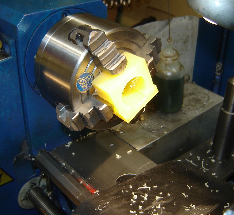 The loupe holder is a piece of HDPE 1.25"x1.05"x0.600 -- my material was 0.830" wide initially and was faced to size later. Also, 1" height material would work fine. The 0.930" hole for the loupe was centered horizontally and the vertical center position is as shown in the drawing. This leaves an opening at the top of the part to pass the non-circular part of the loupe. When mounting the part in the 4 Jaw, a pad was added at the top of the part so it could be drilled and then bored to size, picture at right. The Loupe holder was mounted flush with the end of the short base using 4-40 screws; a sharp tap threads HDPE nicely.
A scrap of aluminum 0.500x0.785x2" was made into a V block with a 0.500" wide V. This was centered on the long section of the base, 0.2" from the end. The center line of the V needs to line up with the center of the loupe hole. Two more 4-40's to secure the V block.
 A bit of 1/8" clear plastic was cut to match the size of the loupe block and attached with (more) 4-40 screws. A vertical fiducial line was scribed on the outside of this such that it lines up with the center of the V block; this line was inked to make it easily visible -- this is easier if the clear plastic is removed for scribing, of course. The screw holes can be slotted to allow fine tuning the fiducial so it is exactly on center - this is critical because it is used to judge whether the drill point is on center. A point 0.450" up from the bottom of the fiducial is marked and additional lines are added to match the profiles of 118 and 135 degree drill points, as seen in the picture at left (click to enlarge).
Assemble the parts and press in the hinge pin to complete the unit.
It helps to have a bright light to illuminate the drill point while using this unit. For large drills, 3/8+ the loupe may not be needed, depending on your near vision.
To check whether a drill's point is on center the base is laid flat and the drill is placed in the V block and slid toward the clear plastic until the drill point is just touching the fiducial line (this minimizes parallax). Look through the Loupe to verify the drill point is on center. If the point is not on center, rotate the drill in the V block and watch to see if the point moves - if it does the drill point may be off center or the drill is bent. Check for a bent drill by laying it on a very flat surface and see whether it rolls nicely or not. While drill sharpeners generally get the point centered, be aware that if a drill is bent then the machine may not grind the point on center.
 To check the point angle of a drill, place it in the V block with the point extending about 1/4" past the end of the V block. Move the loupe to the 90 degree position, then slide the drill in the V block until the tip matches the tip lines. Rotate the drill until the lips are horizontal and check the match with the scribed lines. Generally the drill will match one or the other of the lines -- if not the tip may have a custom angle which can be estimated using the fact the scribed lines are 8.5 degrees apart.
Hand sharpened drills often have the point off center. They may also have lips at different angles so it helps to check the tip angle using the right side scribed lines and then rotate the drill 180 and check the other lip using the same lines - this seems to make it easier to judge, at least for me.
Click to enlarge
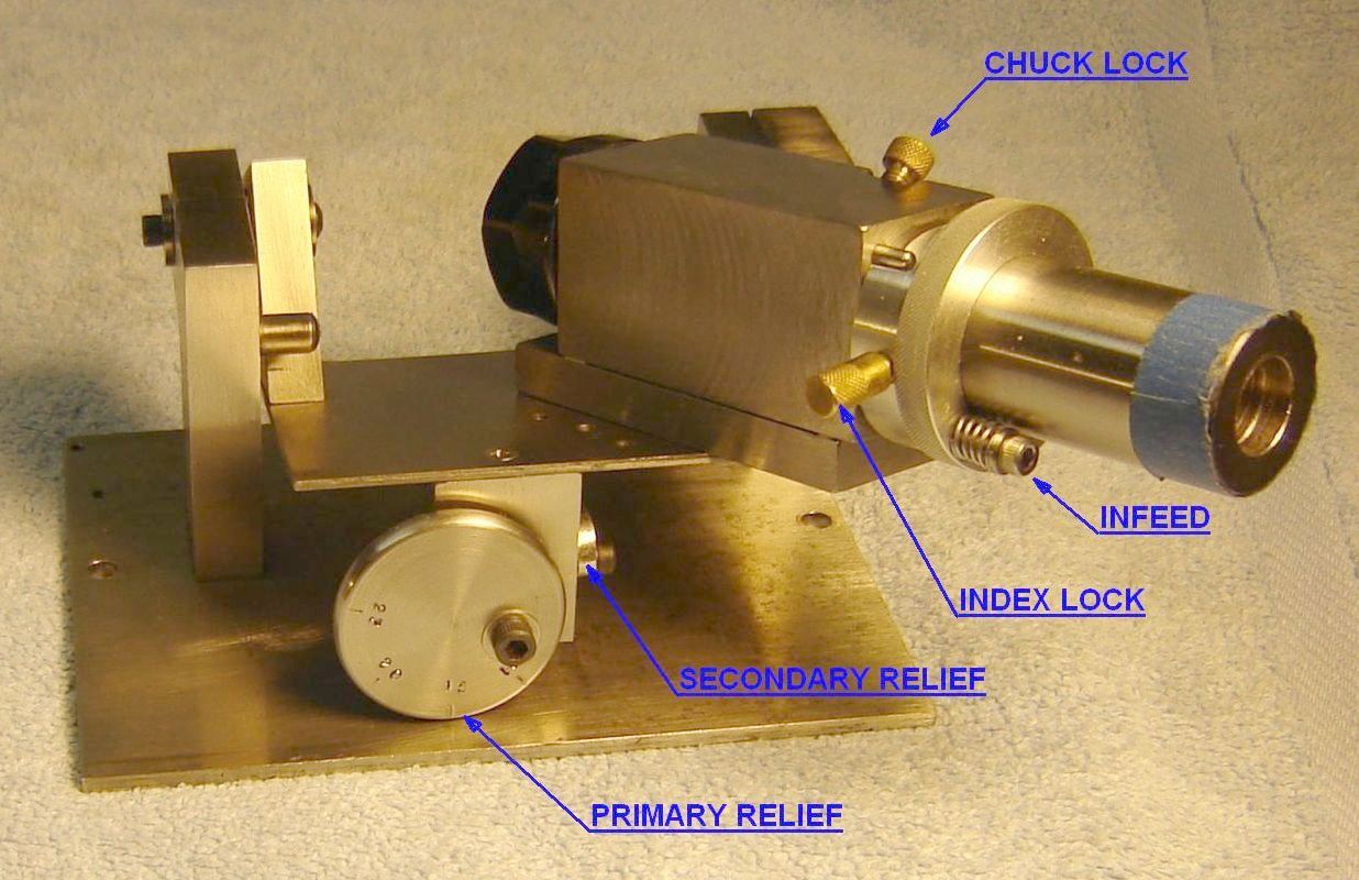
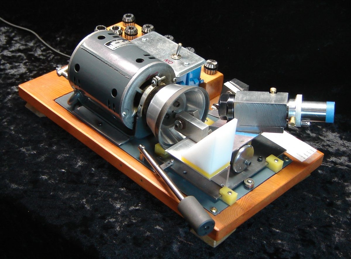
This powered 4/6 facet drill sharpener of my own design covers the range from 1/2" down to 1/16" for 118° and 135° point angle drills. This sharpener is reasonably easy to build and works well so in July 2011 I submitted an article to HSM magazine; it was the cover article for January 2012 - part 2 is in the next [March 2012] issue. The article describes construction of the motion control which can be used with various grinders, as illustrated below. I put a video on YouTube describing the controls and demonstrating their use. (Village Press has run out of magazines containing plans for my sharpener so if you would like to build one, here is a 5.8mb ZIP file containing the sharpener plans.) For those with a 3D printer, see this.
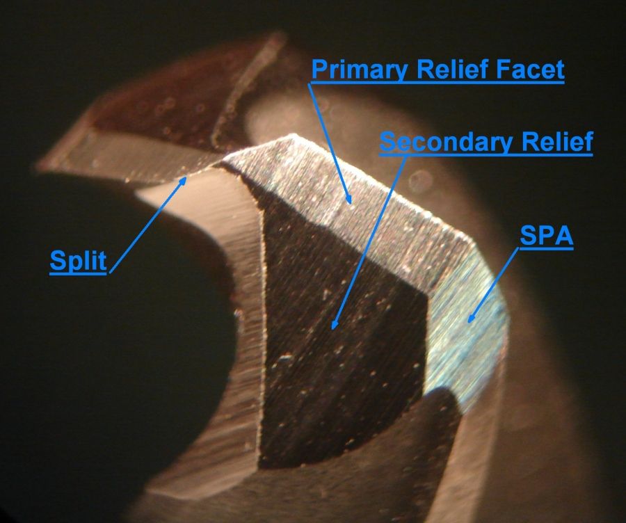
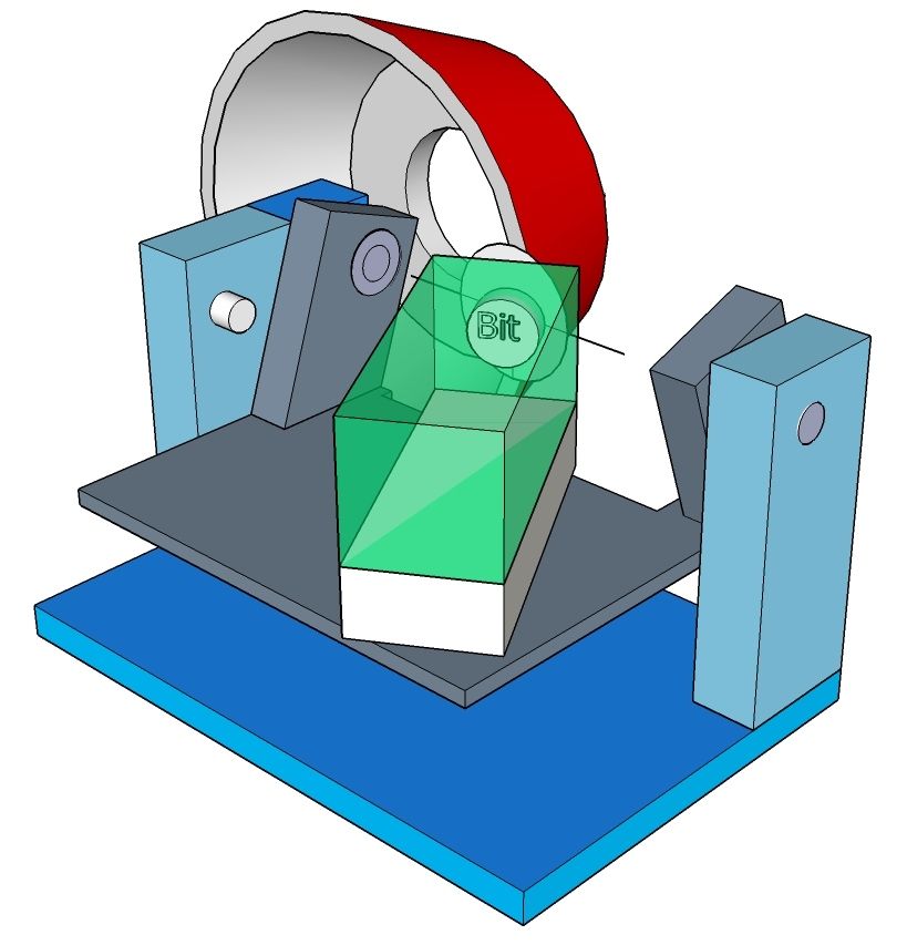
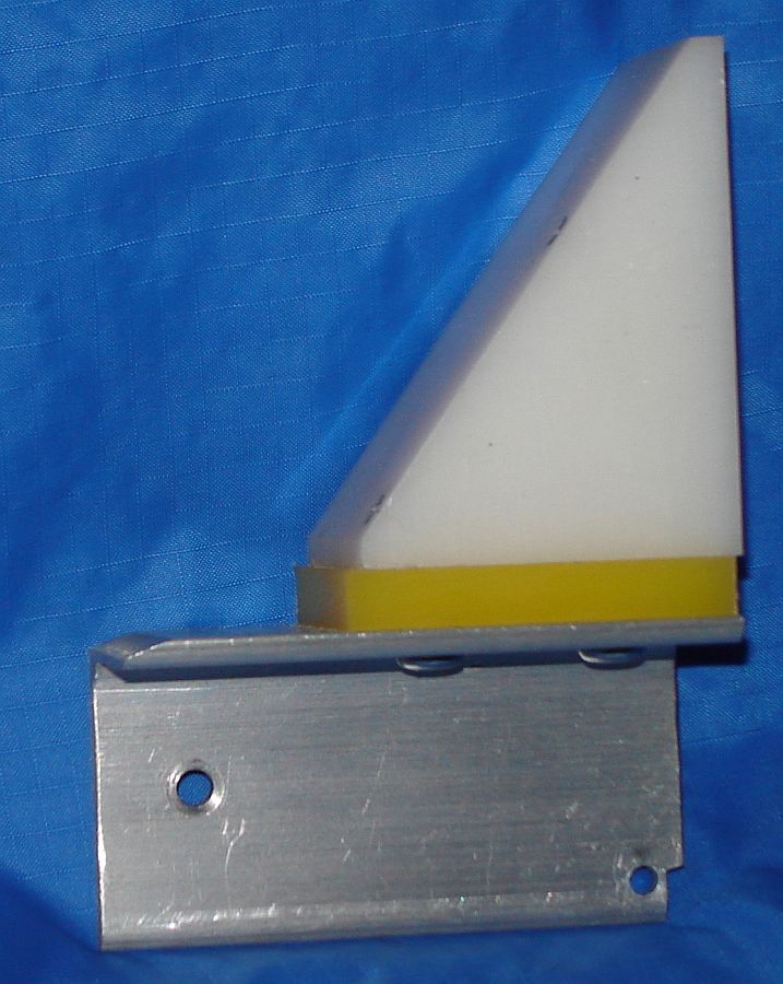
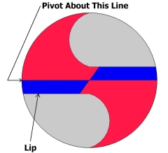 Four facet drill sharpening takes advantage of the fact that the drill's cutting lips are parallel to a line through the center of the drill face and extend in front of this center line; in the drawing at right this area is blue. The blue area is ground at the primary relief angle while the red area is ground at a steeper secondary relief angle so the heel clears the work. All four facets meet in the center of the drill face so the center is pointed rather than the flat chisel common with conical sharpening. This pointed center minimizes wandering at the start of drilling and allows starting nicely in a center punch mark. Secondary Point Angles (SPAs) can be added to extend drill life, improve hole finish and minimize the exit burr on through-drilled holes.
Sharpener Design Goals
This sharpener holds the drill so the facet separation line at the center of the drill's face is on the trunnion table's pivot line (see SketchUp drawing). The wheel's plane of rotation is also aligned on this trunnion pivot line. When the trunnion table is tilted, the line on the drill face doesn't move relative to the plane of the grinding wheel. Drills have material on both sides of this center line, allowing two intersecting planes to be ground, meeting at this line on the drill's face. The trunnion pivot line is shown explicitly in the SketchUp drawing.
Traversing the drill past the wheel grinds it at the wheel's plane of rotation, forming one facet. Tilting the trunnion table to a second angle and traversing grinds a second plane on the drill (the other facet) which intersects the first at the trunnion line. Indexing (rotating 180 degrees) then allows grinding the other side of the drill identically. All 4 facets automatically meet at the center of the drill when the sharpener is correctly aligned.
Infeed moves the drill along its axis relative to the trunnion line to allow grinding more material from the drill (on planes parallel to the previously ground facets).
It is possible to sharpen drills using the 4 facet method on most any cutter grinder, including the Brooks, but it tends to be slow and awkward. The design shown here makes it easy to judge progress - the chuck holder simply lifts off of its locating pins. And, the primary and secondary facets meet automatically at the center of the drill when the jig is properly aligned, unlike the procedure in the above link.
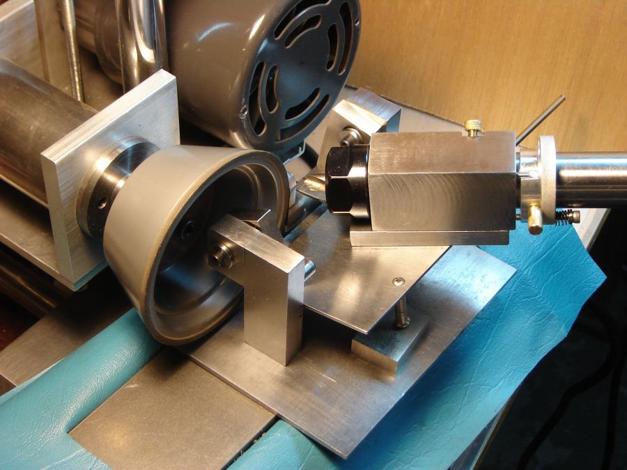
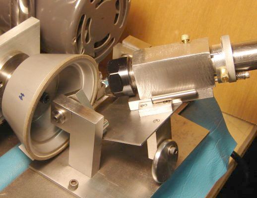
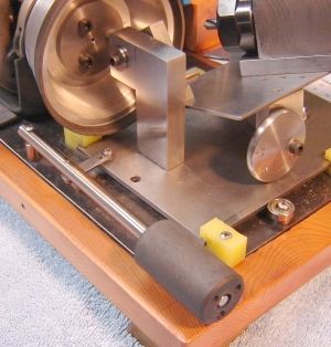
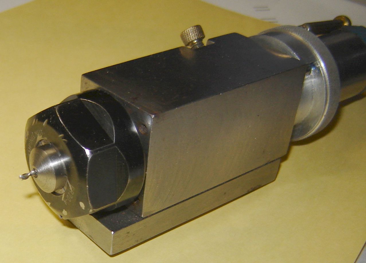
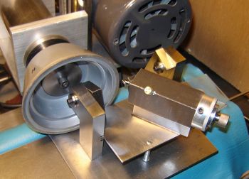 The picture at right shows initial testing using the Brooks wheel and traverse but eventually it became a stand-alone unit with its own motor and simple traverse. As shown here it uses collets from the Honedrill but these were replaced with ER-20 collets+chuck for improved concentricity.
A 3.5" diamond or CBN taper cup is needed for this design since they hold their shape for long periods. Truing an alox wheel would remove a couple thou requiring realignment of wheel to sharpener -- which takes several minutes.
With this 4 facet sharpener it is easy to set (or measure) the relief angle to be ground, no need to estimate relief angle based on chisel angle as commonly done with conical or cam driven sharpeners.
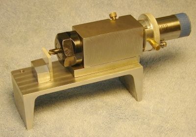
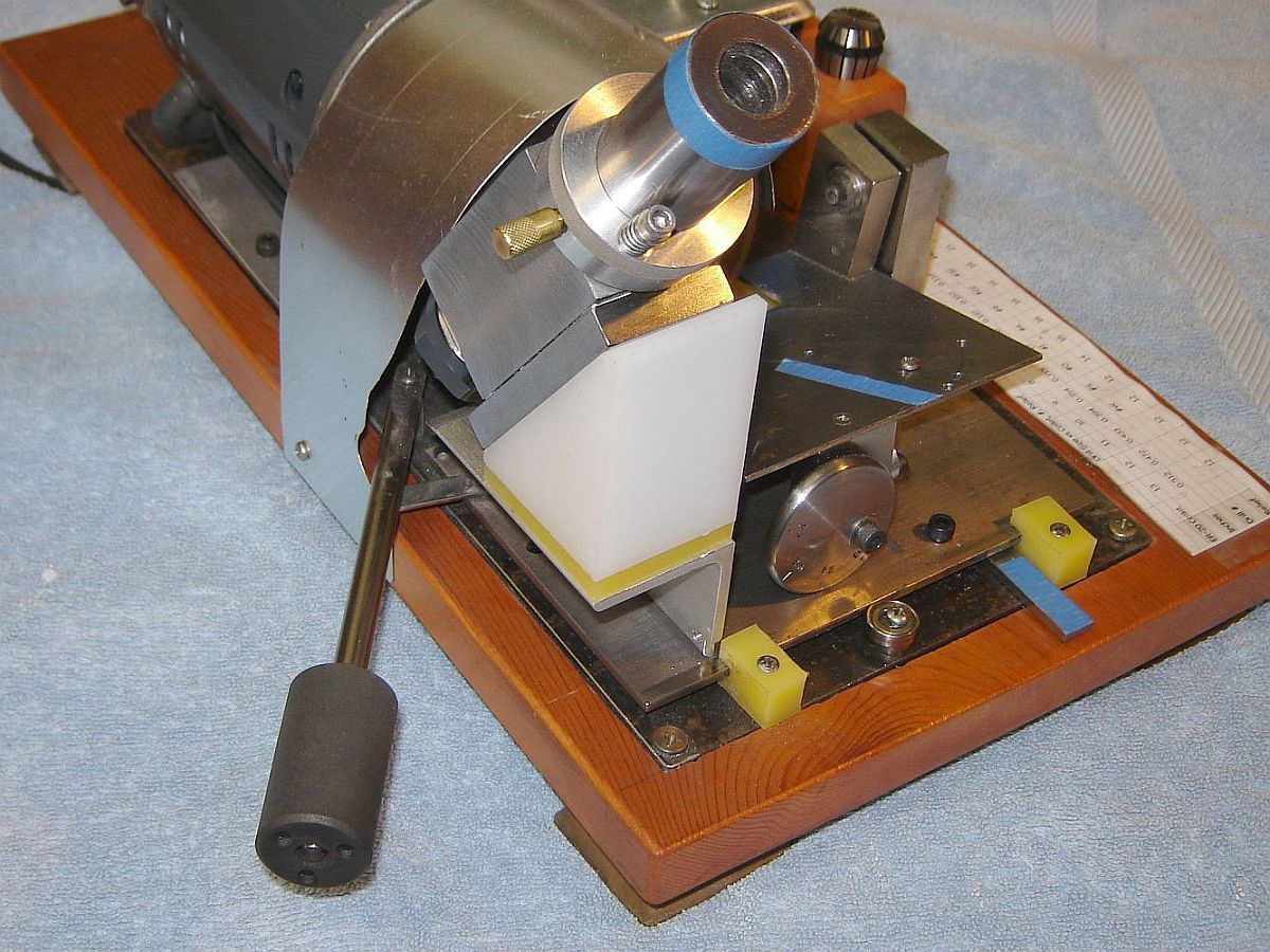
 This is the version using ER-20 collets to hold the drill being sharpened. The pad under the table leg set the primary relief angle for initial testing. A separate jig is used to align the lips horizontal, then chuck holder and chuck are transferred to the trunnion table where the chuck holder's locating pins engage the table. The chuck holder can be simply picked up to evaluate progress, then replaced on these pins.
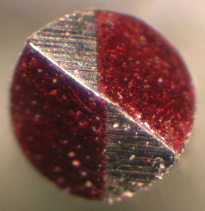
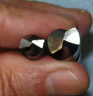
 An eccentric was added and calibrated to allow setting the primary relief angle easily by tilting the trunnion table. The 4 facet sharpener works well for drills from 1/2" down to about 0.060=#53; smaller drills can be sharpened with 2 facets (see below). On the left is an 0.080 test pin ground to evaluate alignment of the wheel to the trunnion table axis; here the primary facets (silver) don't meet properly in the center - the wheel needs to be a couple thou farther from the table to correct this.
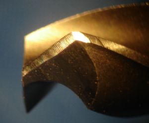 The 11/32" drill shown at right has small SPA's added making it 6 facet. These extra facets cause the drill to have a stronger self centering action plus the shearing action often produces a better finish in the hole. The sharp outer point on the cutting lip, a common failure point (pun), is eliminated so the drill remains sharp longer. It requires only one additional hole in the tilting table to produce SPA's, where the size of the facet is set by eye; SPA facet size isn't critical so simplicity won out.
Note the slight curve in the junction between primary and secondary facets; this is because the (free) motor I used has a rubber mount so it moves away from the drill slightly when grinding the widest part of the secondary relief facet. A rigid mount and a ball bearing motor could eliminate this but it doesn't affect the way the drills cut so again simplicity and cost carried the day.
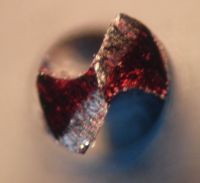 Minimum drill extension from the collet is set by the clearance required between wheel and ER-20 collet chuck while grinding the secondary clearance (tilting table at 28 degrees). Small drills are too flexible to allow sharpening when extended the required amount, limiting 4/6 facet sharpening to drills larger than 1/16"; smaller drills may be sharpened with 2 facets (see below). Initially I wanted to use shop made collets (so the holder could be narrowed to clear the wheel) but found I couldn't make small collets with sufficiently small runout. The picture at left shows a 1/16" drill sharpened in the ER-20 collet; the 100 grit CBN wheel is coarser than desirable for this size drill but note that the facets meet in the center. Unlike the hand powered 4 facet sharpener described earlier, the lips are the same length and the facets meet in the center automatically when this sharpener is properly aligned.
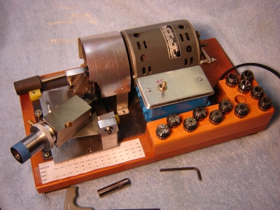
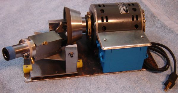 This picture is the beginning of making the four facet sharpener stand alone. The blue box contains the motor start relay; the On/Off switch will mount in the cover. The 94071 grinder from HF (since discontinued) seemed suitable so I replaced the original motor with the HF grinder and it has been fine... although more power would allow faster sharpening.
The primary relief for four facet drills can be selected based on drill size from this simple chart (adapted from Moltrecht). The smallest collet that will accommodate the drill is found by trying it in the collets, then the relief angle is found in the chart based on collet size. The primary relief angle is set by adjusting the eccentric supporting the tilting table to the value from the chart. However, the Mazoff article suggests that drills commonly have excessive relief; a primary relief angle between 5 and 12 degrees works better according to this article - where harder materials drill best with relief angles toward the smaller end of the range. Worth trying as an alternative to the Moltrecht chart.
 180 degree indexing and infeed are handled using the index/infeed ring.
Four and six facet drill points work well (better than conical points in my shop) but they aren't commonly available commercially because it takes multiple passes on a grinder to produce them. Not a problem in most home shops, where performance tops time to grind. This new sharpener design allows 4 facets plus SPA's for large drills, i.e. the best features from the reading and experimenting I've done on drill sharpening. My design differs in concept from anything I've seen but seems accurate and reasonably quick (for 0.035HP) - broken drills need to be reshaped prior to sharpening because of the low power available.
 At left is the traverse lever and link setup. Note the yellow HDPE used for bearings on the traverse - not a conventional approach. Dovetails or ball bearings would be typical but are considerably more difficult to build and need protection from grit. These plastic bearings are lightly loaded, have a very smooth feel, seem impervious to grit, and are cheap and easy to build - takes less than a half hour. The area where the plastic grips the table gets polished but doesn't seem to wear in normal use.
At right is the optional jig used to align the drill lips horizontal and set the initial infeed position. The chuck holder's locating pins fit the jig just as they fit the trunnion table.
A minor issue when sharpening quick change drills which have a hex base: the collet nut must be removed and the drill inserted from the back of the collet - takes a little longer but works well.
Drill point splitting is possible with a modest addition to this 4/6 facet sharpener. Based on the Mazoff article I built a version to produce a "modified split point", similar to DIN 1412 C. My prototype point splitter provides reasonable results considering my wheel's corner is slightly rounded from use. The modified split is angled more than a regular split point and its edge is undercut to provide positive rake. The 6 facet split point drill pictured is 21/64" with a 0.070 web where I left a 0.018 point width (point width is easily adjusted). Per Mazoff the point could be as small as 0.010 and remain strong enough.
 Split points dramatically reduce thrust required for drilling and reduce drift on deep holes. Purchased split point drills generally have a thicker web (25-40% of drill diameter) than normal drills; this makes them stronger but would need increased thrust to extrude the material in front of the web. The split point extends the cutting lip so the web area cuts rather than extrudes. Normal drills have a web thickness of 10-20% of drill diameter, where this relatively thin web needs modest thrust. When this thinner web is split the thrust needed for drilling is further reduced -- if the user applies normal thrust, penetration can be faster than normal BUT the drill may not tolerate the additional forces involved and could split along the web. Users need to control feed rate with normal drills when their point is split, similar to when following a pilot hole.
 My simple prototype drill point splitter is shown at left. Point splitting is a special method of web thinning that extends the cutting lips almost to the center of the drill face. This improves cutting efficiency and reduces the thrust required while drilling.
Below is the optional drill point splitter mounted on the sharpener. It is secured by a single bolt so it can easily be removed if desired. Point width is set using a tapered stop, seen near the right rear bearing; blue tape marks the position for 20 thou point width. Sliding this stop farther out from under the traverse table narrows the drill point. This stop is removed to change from point splitting to sharpening mode.
The split point produced may be adjusted considerably via: rotation angle, infeed, and point width.
Drills smaller than 1/16" or so extending the normal 0.45" from the ER-20 collet may flex and vibrate when sharpening is attempted. This can cause the drill to "catch" on the wheel and break so it isn't a viable way to sharpen small drills. Small drills must be held closer to their point to avoid this problem but the ER-20 chuck then conflicts with the wheel when inclined to the secondary relief angle. Drills down to #60 can be sharpened by grinding only the primary facets, i.e. similar to standard sharpening. A primary relief of 15° works if the extension from the collet is set at 0.170" or so. This allows sharpening small drills but requires care to avoid contact with the chuck nut - it clears the wheel by only 1/16" or so. Although the benefits of 4 facet sharpening are lost, it is possible to sharpen small drills acceptably with this approach. Secondary relief facets can be added with a hand powered jig if desired.
A better approach is to use the tiny collets from the 4 facet hand powered sharpener via a round collet holder which is held in an ER-20 collet. This collet-collet scheme works nicely to put 2 facet points on tiny drills quickly and easily. It does require the sharpener's alignment to be VERY accurate since even small alignment errors can cause the point to be off center. And alignment is even more critical on 4 facet points.
 The small collets shown at right were originally made for the 4 facet hand powered sharpener where you can find information on making them and the collet holder. The round version of the collet holder is 1.6" long; I used 1/2" round stock but anything 3/8" or more should do. The hole for the collet must be accurately centered since any error here will affect the alignment -- so it's worth a little fussing to get this right. I put a 15 degree angle on the front of the holder to within 1/16" of the hole, this to improve clearance in use.
 Operation is similar to sharpening larger drills with some minor differences. Choose the appropriate collet for the small drill to be sharpened, load it into the round holder and add the collet nut. Insert the drill with an extension of about 1/8" from the collet holder and tighten the nut to secure the drill in the small collet. Insert the round collet holder into the appropriate ER-20 collet but don't tighten. Use the regular tool to set the extension of the drill point from the ER-20 collet and tighten the ER-20 collet nut. Use the alignment jig to set the lips horizontal - a strong magnifier may be helpful. Sharpen as usual but expect very quick sharpening with these tiny drills. Look carefully at initial results to ensure your sharpener's alignment is correct and tweak if necessary. The picture at right shows this setup; note the dings on the ER-20 nut from oops while sharpening small drills without the small collet scheme.
Small drills are sometimes broken in use. Grind the broken end flat on a bench grinder to simplify setting the lips horizontal. Then make a pass with the sharpener; check and re-adjust the lips horizontal (if needed) and complete sharpening.
I often use #1 center drills for starting holes but find them relatively fragile. Should the tips snap off they can be re-sharpened to resemble a spotting drill (but with 4 facets) -- and are much less fragile than they were originally.
I researched and tinkered with building drill sharpeners for over 5 years prior to building this sharpener. The material below on using drills is partly from experience and partly from things I read during my research that made sense to me and I hope makes sense to others...
Cutting oil is helpful for drilling in steel and most other metals. WD40 works well for aluminum.
A spotting drill works better than a center drill for starting holes accurately. A spotting drill should have a 4 facet or split point to minimize walking and the point angle should be larger than the point angle of the drill which will follow. Otherwise the following drill can contact on one lip and pivot away from the desired location despite the divot from the spotting drill. Using a 135° spotting drill for a 118° following drill avoids this - the drill point will touch first and locate into the bottom of the divot. If the following drill has a 135 degree point then one extra hole in this sharpener will allow grinding a 144° point angle on the spotting drill and this can be used to center 118° or 135° points. A center drill, especially one with a broken tip, is easily converted to a spotting drill with the characteristics suggested here. Spotting drills should be used only to produce a divot smaller than their diameter; if the drill penetrates then the following drill's lip can catch on the edge of the hole rather than the tip locating into the divot.
Most of the thrust required for drilling with a chisel point drill is used to extrude material in front of the chisel since the chisel can't cut. This can force the drill off line causing the hole to drift. Reducing the required thrust results in straighter holes. While 4 facet points reduce thrust slightly, the material is still extruded. Split points are more effective in reducing thrust because the web area cuts rather than extrudes; this is also more efficient so it reduces heat produced and prolongs drill life. (See Moltrecht pg. 91-93, especially Fig 4-13)
Pilot holes help locate a hole properly and work well for reducing thrust. The pilot hole should be slightly smaller than the web of the drill to follow. This minimizes thrust for the larger drill while allowing its web to be guided by the pilot hole. Alternatively, a split point drill reduces thrust needed considerably and may be faster because it is a single operation.
Drilling a hole to accurate size is best done by drilling one size under and then removing the small amount of material remaining with the final size drill. Using a drill with SPAs works well for the final pass, cutting to size and leaving an almost reamed finish. When hole finish is important, stop the drill prior to withdrawing it. For really accurate hole size drill a few thou under and ream to finished size (assuming you have the needed reamer). One issue I've had with SPAs is they don't work well in aluminum bronze bearing material, where regular drills work fine.
Drilling to accurate size in one go is possible but tricky. As drilling starts the drill isn't constrained by the lands touching the hole; extra thrust is helpful because it causes the point to stay fully into the cone. A split point helps by providing more cone area and encouraging rapid penetration with modest thrust. If thrust is relaxed the drill often attempts to cut a reuleaux triangle as first one lip and then the other catches, causing the drill to ricochet around in the hole. When this is happening, if you stop and look at the cone in the hole you'll often find 3 or 6 lines radiating out from the center of the (oversize) hole. Once depth is greater than about one diameter things usually settle down but this early rattling around can cause an oversize or bell mouthed hole. Accuracy in sharpening is needed for size accuracy - drill point concentricity and symmetry are necessary, SPA's and point splitting improve results and make drilling technique less critical.
Brass can be drilled with regular drills but requires care to avoid hogging in. Brass simply drills too well - the flutes can augur into the work until they can't cut or the drill breaks. Avoid split points, the extra thrust needed to extrude the central material helps to prevent auguring. Reducing the primary relief helps too. Dubbing the lip's cutting edge lightly to eliminate rake (i.e. the cutting edge becomes a few thou thick) is a time honored way to avoid hogging in - the drill essentially scrapes rather than cuts.
Soft plastics like Delrin, nylon, HDPE also cut too well, similar to brass, so the same methods are helpful. Plastics are prone to having the point of the drill break through and then the outer part of the hole catches the lips and the drill augurs in. A large SPA can be helpful in minimizing this since it is a form of exit burr. Soft plastics often produce long chips so pause frequently to break the chip. Plastics can heat the drill more than expected so check often and adjust drill speed to minimize heating.
Brittle plastic like Lucite, according to Mazoff, benefits from a drill point over 140 degrees to minimize auguring and breakage of the plastic. Thermoplastics like Lucite benefit from reduced RPM plus lubricant or coolant to avoid melting while drilling.
I put a video on YouTube so potential builders can get a feel for how the unit works. This section will cover changes made since publication of the HSM article, some inspired by feedback from builders.
Pre-publication copies of my 4/6 Facet Sharpener article's files were sent to a couple builders for comments and to verify the build procedure. Several helpful comments were received plus one issue surfaced concerning calibrating the 180° rotation. 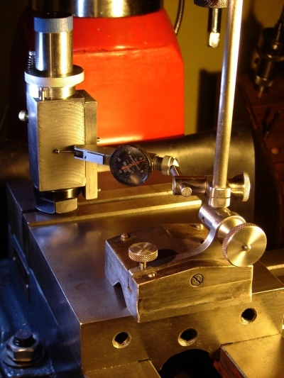 Apparently I got lucky on this because my rotation was within a quarter degree. Depending on the build method used it is possible for rotation to be several degrees different from 180, causing the chips to differ considerably between the two sides of a drill after sharpening. Australian builder Brian S. suggested a simple test for 180 rotation that is very sensitive. My version of this test (see picture) requires the sides of the collet holder to be parallel, which they were because I had fly cut them. (There are other, similar ways to check rotation, e.g. using a DTI held in the mill spindle.)
A pin is gripped in the collet and then the chuck holder assembly is held vertically in a vise by gripping this pin as shown. I used a surface gauge with the locating pins running on the front edge of the vise's movable jaw as a reference. The DTI finger touches the side of the chuck holder, allowing the side to be set parallel to the front of the vise. Once parallel the chuck lock is used to hold it in place, then the index ring is rotated against the stop, lifted up away from the chuck a few thou and locked to the chuck. The chuck lock is released and the chuck holder rotated so the index pin is against the other side of the ring. The chuck is locked and the DTI is used to verify that this side of the chuck holder is now parallel to the vise front edge. If the rotation is not 180° per this check, rework the index ring or replace the index pin with one of the diameter needed, sizing one end to fit the 1/8" index pin hole.
I purchased the collet chuck and collets from CTC Tools:
Collet Chuck F95
ER-20 Collet Set
Shipping is expensive so try to get everything from CTC in one order. The ER-20 collets hold items to 1/2" so (if your machines can use them) consider MT2 and/or MT3 shank chucks in addition to the 1". Builders often have ER-32 collets in their shops so would like to use them rather than ER-20; two issues arise: the nut is much larger so conflict with the wheel at the secondary relief angle causes difficulty and the torque needed to properly close an ER-32 is very high.
The prototype used a 3.5"/90mm D11V9 wheel. Inexpensive D11V9 diamond wheels are more common in slightly larger sizes, 3.75" and 100mm (e.g. see Shars). To accommodate these slightly larger wheels, increase the height of the table supports by half of the diameter increase. E.g to use a 4"/100mm wheel increase the height from 2.375" to 2.625". The wheel should clear the traverse table by 1/8" or slightly more. If the optional point splitter will be used with a larger wheel, the traverse table may need to be a bit longer also...
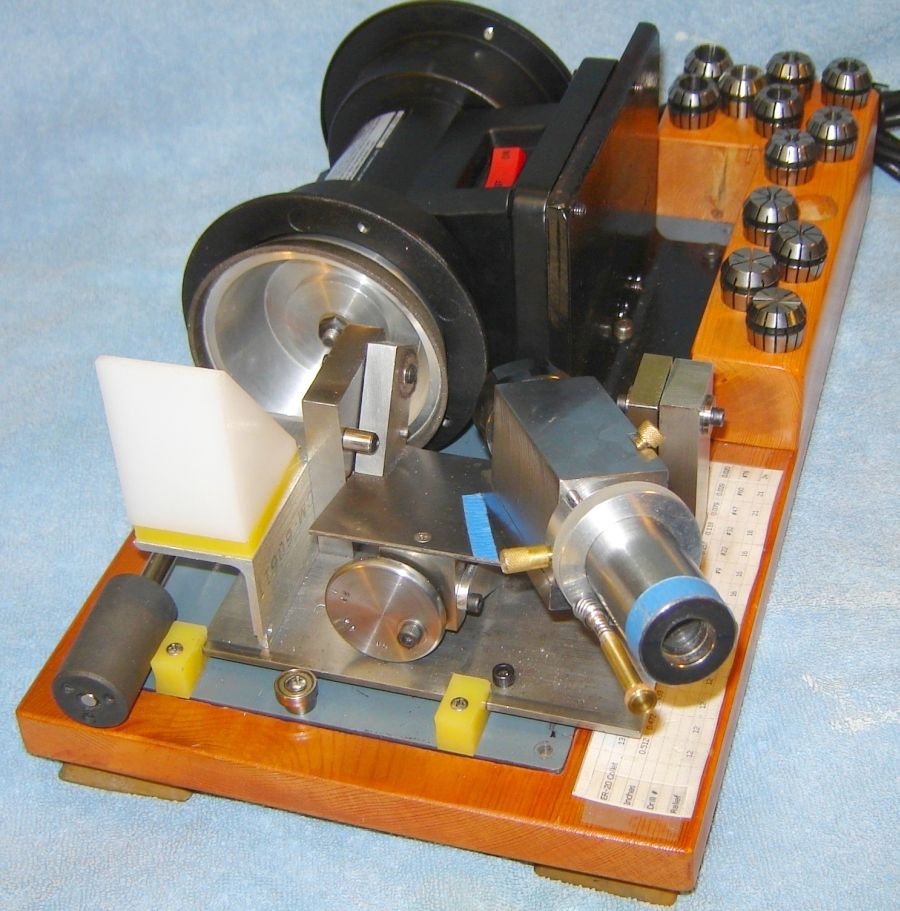 I replaced the motor with a HF 94071 (discontinued); seems OK, the ball bearings work better than the plain bearing in my original motor. It is clearly more powerful -- grinds faster but makes a little more noise because it's higher speed. So far, this motor handles the repeated start/stop cycles needed when sharpening drills. Although the label claims a 1/2" arbor, the measured diameter of the arbor on my unit is 0.394" = 1cm.
It is straightforward to fit the motion control to a specific motor and mounting plate. However, in replacing my original motor the minimum work approach was to place the new motor so the wheel has the same relation to the motion control as it had with the original motor. The 94071 wheel, even with the rubber feet removed, is higher than with my original motor. So, I mounted it using a scrap of angle iron to which the motor base sans feet was bolted. The angle iron was trimmed to fit the space available. Spacers were added under the angle to set the wheel height to match the original. I had to remove the holders for the tool rests and reverse the motor on its base so the wheel rotates CCW and the switch is accessible.
Builders who opt for this motor would normally skip all this, remove the feet and bolt the motor to a small plate to allow adjusting the wheel position vs the trunnion line (the switch would be on the left side). This plate would be bolted to the base with slots to allow adjusting position vs the wheel. The height of the motion control would then be set appropriately.
In any case, a couple additional details need attention. The motor shaft is slightly too long such that it would contact the left trunnion holder. I removed the rotor by removing the right end cap, chucked the left shaft (with protective material to prevent marring it), used the steady to hold the right end of the shaft, and shortened the threaded section about 1/4". The quick alternative: use a bench sander to shorten it. When re-assembling the motor, place the spring washer on the right (wheel) end (mine was on the left end originally). An appropriate wheel adapter needs to be fitted for the taper cup wheel, of course. I used 6061 aluminum; make the 0.625 a little longer and face to length so the wheel clears the grinder's guard by about 1/8" and make the ID a light interference fit on the grinder shaft.
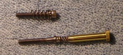 My original infeed screw used an Allen wrench for adjustments. I made an extended infeed screw with a spring soldered in the middle so it wouldn't be easily damaged. Works well, makes infeed adjustment more convenient.
Point splitting requires the drill extend farther from the chuck than sharpening. This magnifies the effect of any slight bend in the drill and any minor error in how the collet grips the drill. This can cause the split to be asymmetrical. It can be corrected by proceeding to grind each side alternately until the more advanced side is at the desired position relative to the drill point (where the facets meet). Then, grind only the side which needs to move further toward the center by pulling the point width taper out slightly. Proceed in small increments, examining the point after each, until the split is symmetrical.
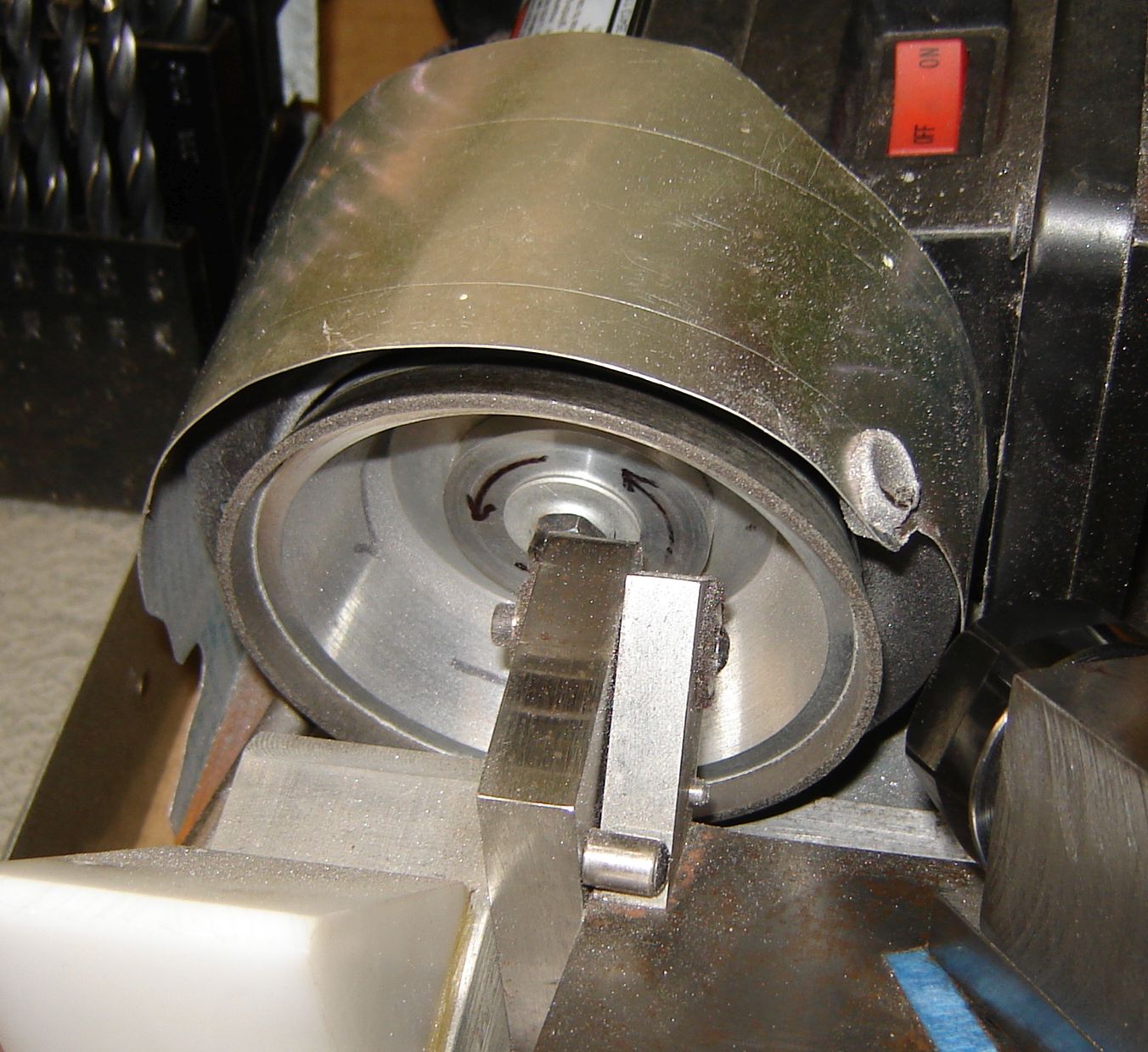 The CBN wheel produces a fair amount of very fine metal dust from the drills it sharpens. This dust is propelled upwards and gets all over the sharpener as well as in the air where it is not healthy. I have a very thin flexible aluminum cover over the wheel in an attempt to deflect the dust down, minimizing the spray of fine metal particles. I added two neodymium magnets to this aluminum shield just above where the dust is generated (picture at right) - this worked great, trapping the majority of the metal dust. The dust builds up quickly on the magnet inside the shield and needs to be cleaned frequently when sharpening large drills. At one point I let it build up excessively and the dust suddenly began to glow red - apparently a spark from grinding caused a small fire in the metal dust. This was enough to flake the shiny plating off the inside magnet. The inside magnet has been replaced with a piece of steel, where the outer magnet is strong enough to cause the steel to capture the dust. And I'm now careful to keep dust buildup on the steel under control.
I occasionally visit a small local machine shop where they tolerate me and sell or give me bits of material needed for my projects. In order to figure out whether drills I sharpen work well I asked if I might sharpen a few drills for them and get their opinion on performance. They agreed and also demonstrated hand sharpening on one of the drills I was to sharpen. Their result was surprisingly good, better than any hand sharpened drill I had come across, as judged by beginning grinding on my jig and looking at symmetry. So I sharpened a half dozen drills of various sizes for them and returned a couple weeks later to see how they worked out. They were surprisingly happy with the drills I sharpened, in particular noting that the SPA's seemed to improve drilling considerably. They asked me to sharpen more drills for them, adding SPA's. I sharpened an index full of drills for them and checked back several months later. They're still very happy with the drills I sharpened - they are staying sharp longer than the drills they hand sharpen plus they indicated the drills with the SPA are "more stable" in operation, i.e. less tendency to chatter. Holes are much closer to size than with their hand sharpened drills.
Which brought up an issue I hadn't considered. This sharpener works well in my shop because I immediately sharpen any drill that seems dull in use, meaning I sharpen drills now and again rather than many at one time. With the 1/10 HP motor it takes 3-8 minutes to sharpen a drill, depending on size and condition. Not a problem the way I use the sharpener but when sharpening an index of 30 drills it takes hours. And most of this is grinding rather than setup - the little 1/10 HP motor slows down, limiting the grinding rate. Bottom Line: more power is needed to use this unit commercially. A grinding spindle and 1/4 HP motor in a setup similar to the Brooks might work well.
Based on my description of building this 4 Facet Sharpener and the article in HSM I hear from others who would like to build one. I try to answer questions that arise and aren't covered by my article or the above description and generally stay in touch with other builders, some of whom keep me abreast of their progress.The pictures illustrate variations on the original design, where the underlying concept is preserved.
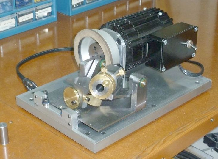 Jim Schroeder is a talented and energetic machinist, having completed a Brooks cutter grinder and now a 4 facet drill sharpener. It works well and he expects to add the point splitter shortly. The ball bearings for the traverse table work well but require frequent cleaning of grit from the table to ensure free movement.
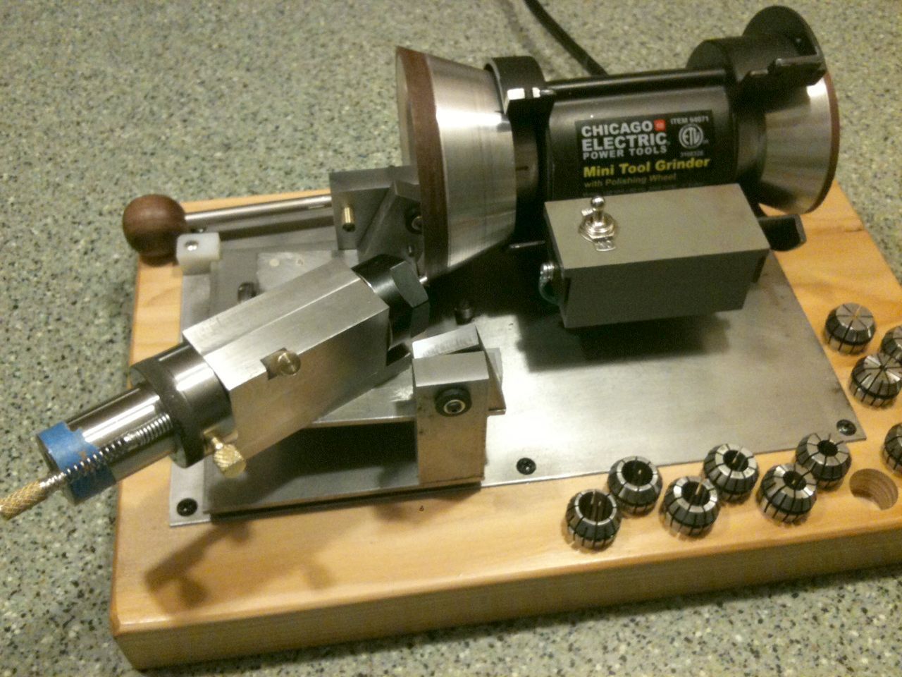 I met Rodger Young at Cabin Fever 2012 where I displayed and demonstrated my 4 facet sharpener. Rodger had just begun construction at that time and was interested in seeing the unit in action as well as discussing various points in its construction. Less than 5 weeks later it's complete - fast work considering the time it takes to get collets from China.
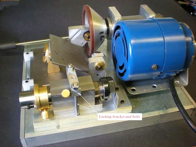 Leon Dionne built a Broadley spindle rather than mounting the wheel on the motor shaft. The base is galvanized steel with a 1/2" aluminum frame. He made the lip alignment jig so it bolts down to secure the collet chuck holder during transit.
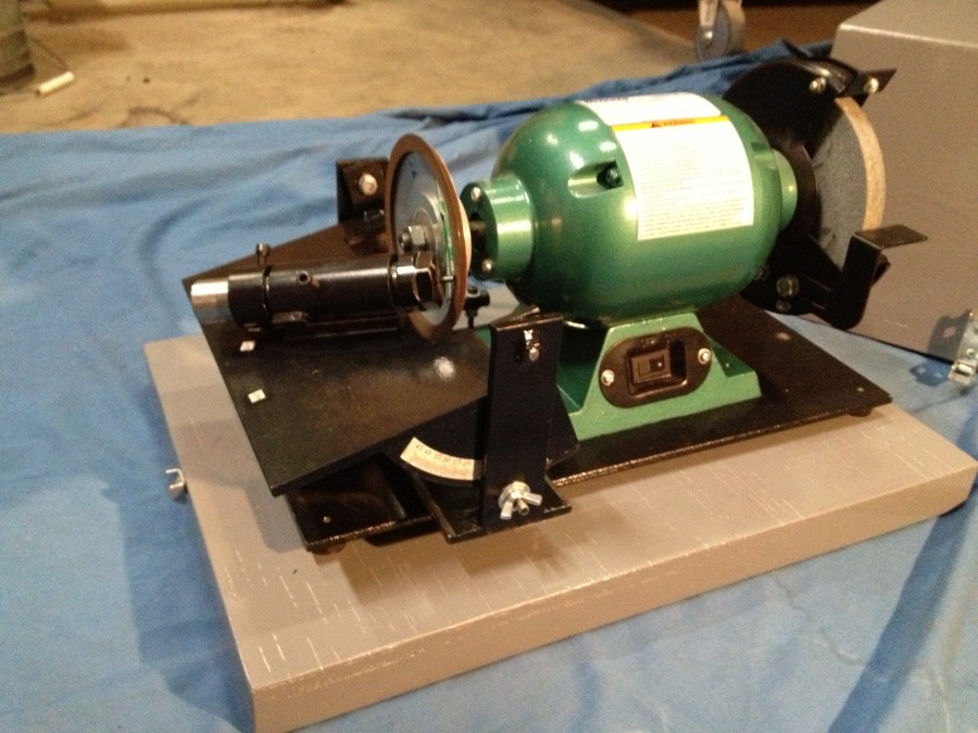 Robert Simpson used a Grizzly 6" bench grinder for power; construction is welded rather than bolted together. The trunnion support is higher so the drill's axis can point up and to the right for better visibility while sharpening. Rollers are used rather than plastic slides. Point splitting is done at the secondary point angle by first rotating the drill on its axis. He made a case that attaches to the base for protection during transit and storage. Click image to enlarge.
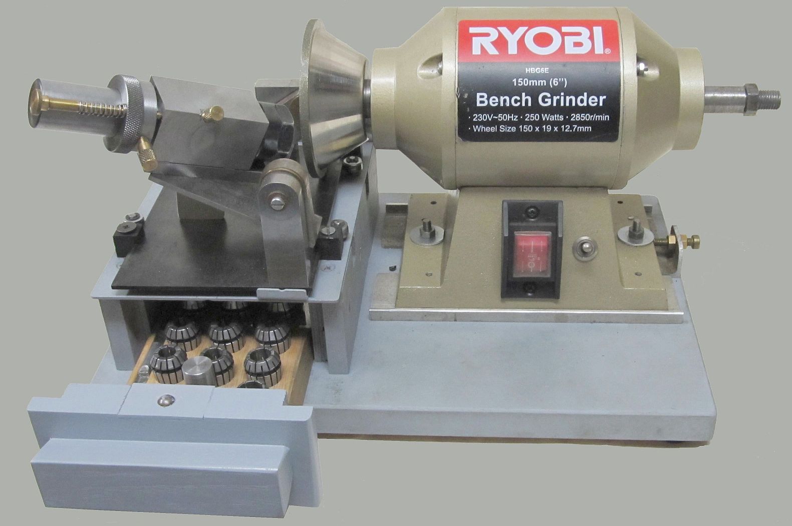 John Robertson used a Ryobi 6" bench grinder for power. Note the adjuster to set wheel at trunnion pivot line. The drawer to hold the collets is a nice touch. Click image to enlarge.
 Mark Frazier used the small Harbor Freight grinder for power; construction is mostly aluminum with brass accents. His friend made the base and collet holder from walnut, which adds a nice touch.
Subsequently, Mark made a somewhat revised version of the sharpener from steel, used linear bearings and detailed his build at Hobby-Machinist (where you may have to join to access it).
 Ron Behrmann is in South Africa (no Harbor Freight there) so he used a different grinder for power. Mostly aluminum, excellent machining especially the knurling. He used a different method to set the relief angles to discrete values, as pictured here.
 Bill Kennedy used the concept but implemented quite differently. The primary relief angle is set by locking the trunnion table to the arc. Indexing the drill by 180° is handled by unclamping and rotating the octagonal chuck holder in the V block; infeed is controlled with the micrometer stop. The X-Y table's Y feed is used to align the trunnion table's pivot to the wheel, X feed moves the drill point past the wheel. Bill worked from the concept description above; he didn't have the HSM magazine article or a copy of my file describing the build - a surprising feat of reverse engineering.
 John Dunbar used a more powerful Harbor Freight grinder for power. Construction is mostly aluminum.
In this version the grinder is fixed to the base plate and the platform holding the trunnion table is moved toward or away from the grinder to align the trunnion table's pivot to the wheel.
 Bob Rawlins from Australia also used a more powerful grinder for power. Construction is mostly aluminum.
Here the grinder is fixed to a wood base and the trunnion table is raised to the wheel's center height. This provided space for a nice drawer to hold the collets and other tools.
 John Baron made the table wider so the left table support is outside the wheel. He used ER16 collets rather than the original ER20's. The motor is reversible, accounting for the two switches on the top of the box. Lots of little differences from the original design but it keeps the original concept where the drill center is on the trunnion pivot line so it works fine. He also made the jig to set the drill extension from the collet and the lips horizontal
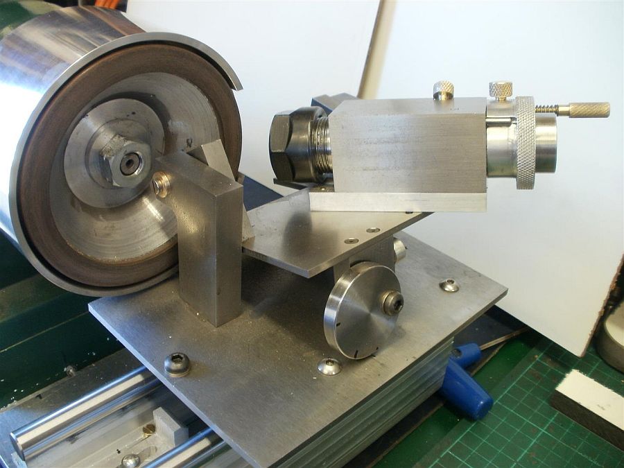 Ian Johnston used linear bearings rather than plastic bearings for the traverse; the chuck holder is cast iron. The custom shield around the 4" diamond wheel is a nice touch.
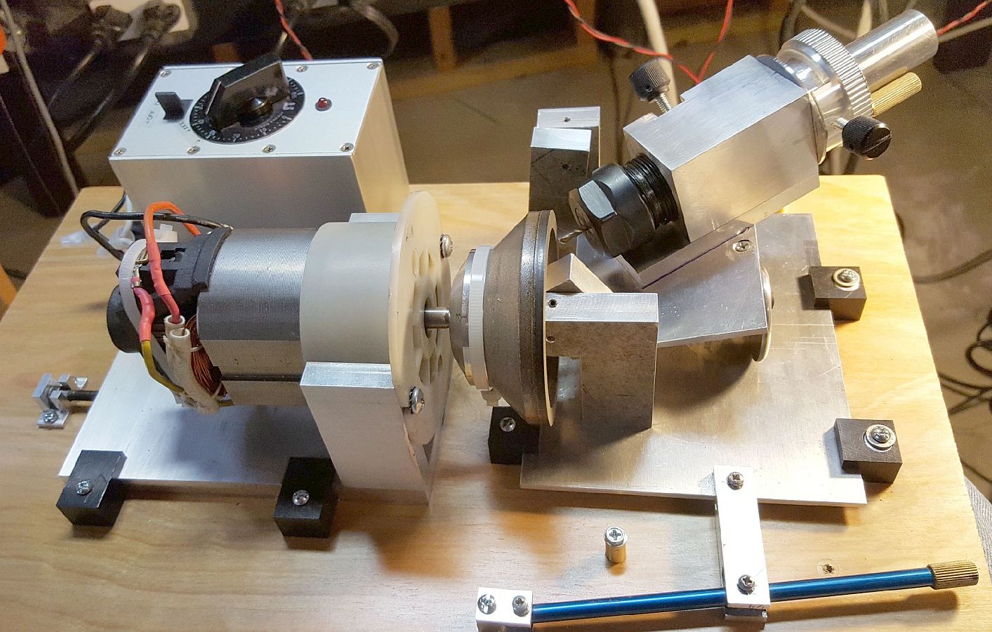 John Trepp used mainly aluminum plus wood for the base. The motor needed a speed control so he designed and built that too. Note the adjuster to move the motor/wheel to align the sharpener. He added a light spring between the collet nut and the block holding the chuck to keep the infeed screw against the block -- and then added a large steel washer for the infeed screw to contact so the aluminum block doesn't wear. Lots of interesting details in his build to accommodate the material he had on hand.
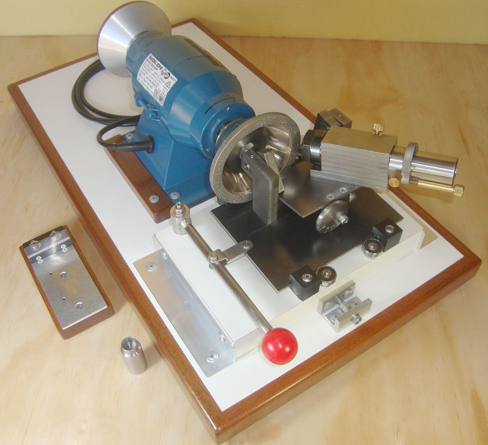 Alan Grimes fixed the grinder to the base and made the overall table assembly movable, a different method of aligning the wheel to the trunnion center. He reports excellent results with 6 facet drills. The woodwork on the grinder base and alignment jig are very nicely done making this unit a showpiece.
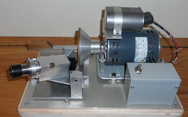 Gordon Dick uses a 1/3 HP motor in his sharpener. The motor is mounted on a metal plate whose position is adjusted with a bolt at the rear to simplify alignment of the wheel to the trunnion center. Collets are stored in a separate wooden block.
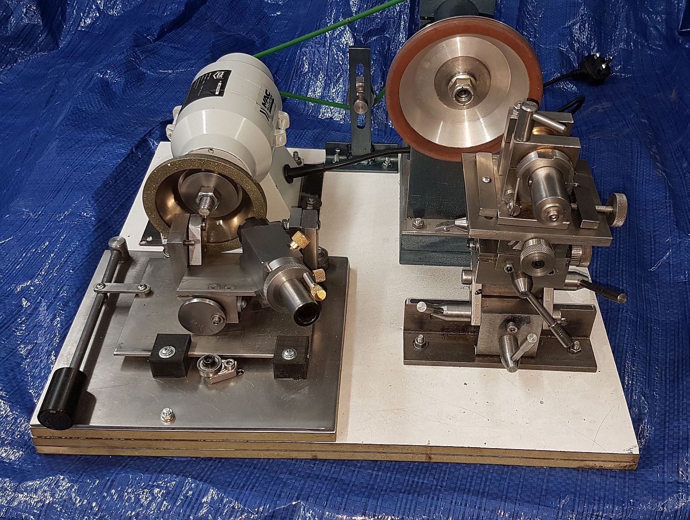 Derek Toller drives both the 4 facet sharpener and a Harold Hall grinding rest from one grinder using a belt to drive the arbor. The grinding rest is fitted with Harold Hall's end mill sharpener so Derek is equipped to sharpen many tools with this setup.
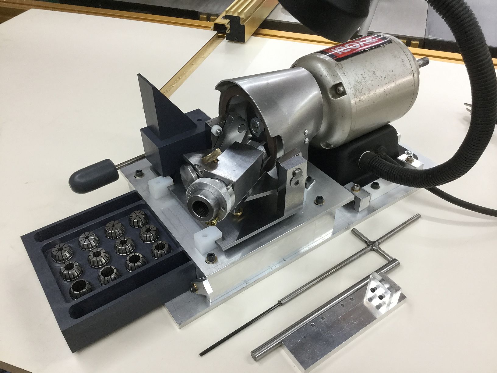 Paul Muensinger is a meticulous craftsman and a member of our local CTHSM group. Note the nifty drawer for collet storage. Paul included a picture of a drill he sharpened with SPA and split point.
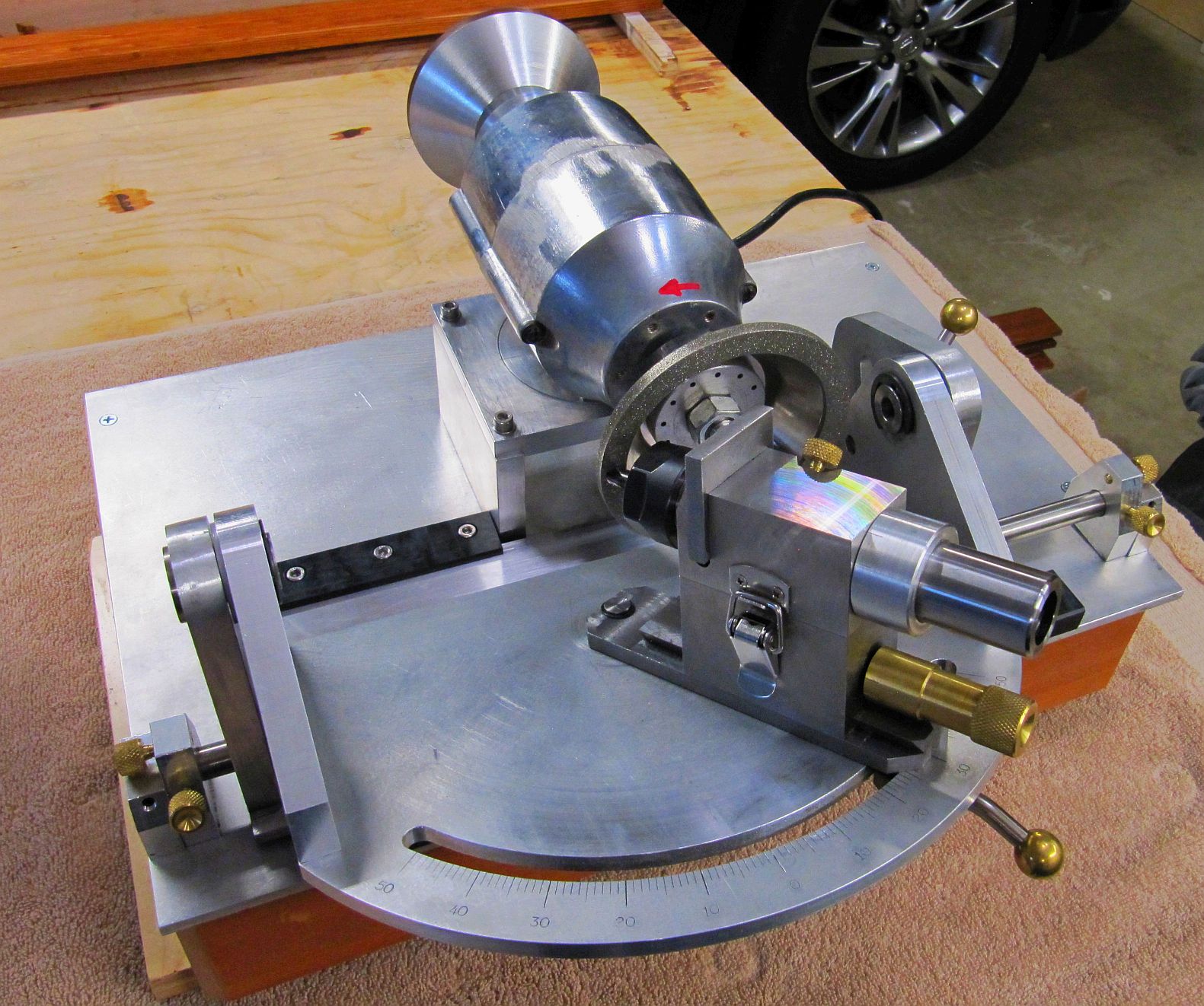 John Lamb made a "few modifications" while keeping the underlying concept. His version allows adjusting the point angle through a considerable range, allowing him to sharpen lathe bits and he also plans to sharpen end mills. He reports the diamond wheel rapidly sharpens drills.
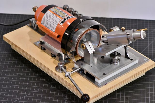 Cecil Huey uses a different method for table bearings and guidance as seen here. The plastic bearings bolt to the table while the adjacent metal brackets have a lip which fits into a slot in the bearing. The central guide bar is bolted to the table and the ball bearings fix its position so it can guide the table in a straight line. This picture shows the differential screw mechanism which provides fine adjustment of the wheel vs the trunnion table. A Lexan shield and several other interesting details in this unit.
 Alan Wood used a 3D printer to produce many of the parts for the 4 Facet sharpener. This reduces the effort needed to make a sharpener considerably and, if any plastic part should wear, you could then make a replacement from metal. Alan put a lot of effort into this and shares a description of his efforts as well as files needed to produce the parts on his site.
Click to Enlarge
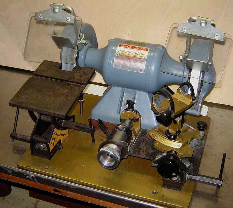
I found this Darex M3 drill sharpener on Craigs List in March 2009. It is different in principle from the Pit Bull in that it uses a cam to guide the bit across the wheel circumference in a complex motion. Plus it has an accurate method of setting the bit's angular position in the collet as well as a nice method of advancing the bit (unlike the Pit Bull). Results are good for bits 3/16" or larger but it gets trickier with small bits.
I now use the powered 4/6 facet sharpener described above for most drills although I continue to use the hand powered sharpener for drills under 1/16". SPA's are added to drills larger than 1/8" using the motorized 4 facet sharpener so the HoneDrill isn't used much any more.
The Darex M3 doesn't include point splitting as their more expensive M5 does so when needed I split point drills with the 4/6 facet sharpener's point splitter. I no longer used the Darex after completing the 4/6 facet powered sharpener so I sold it in January 2012.
Click to Enlarge
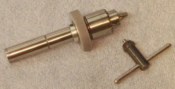
A sensitive drill attachment facilitates drilling with tiny drills, where the loss of "feel" using a drill press or a tailstock handwheel often leads to broken bits. This attachment allows drilling with finger pressure applied via the knurled ring; the knurled ring is isolated from the chuck by a ball bearing so it doesn't rotate with the chuck. A spring retracts the chuck when finger pressure is relaxed. The Jacobs chuck shown accommodates bits up to 5/32" or 4mm.
Plans for this sensitive drill are found in the Photos section of the Groups.io 7x12MiniLathe Group as "Drill Adapter Plans". I roughly followed those plans but shortened the outer body to 2" and used a washer between the knurled ring and the chuck. Extension with my version is 5/8", sufficient for depths that I drill with tiny drills.
I built this from scrap so it was necessary to take some liberties with the design, 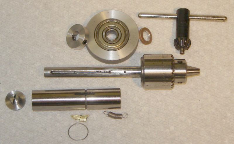 plus some minor changes would make it easier to build with the tooling I have available. If I were building again I'd try a 3/8" body rather than 1/2" to make cutting the slit easier - I don't have a 1/16" end mill so I used a 1/16" Woodruff cutter to make the slots - a thinner body would make this easier. I used a 608ZZ bearing so it was necessary to use a bushing to fit it to the 1/4" internal shaft.
For those who would like to build but don't want to reference the plan on Yahoo, here is some build info (see picture above). The Body is 2" long (1/2" or 3/8" OD), drilled to 0.243 and then reamed 0.250 half way through from each end. It is important to drill from both ends, centering carefully each time to ensure concentricity of the bore. When reaming the second half, run the reamer all the way through. A 0.035 wide groove, 0.030 deep is turned 0.865 from the lower end of the body. A 1/16" wide lengthwise slit is added beginning 0.6" from the lower end; slit length is about 0.6". My arbor is 1/4" drill rod 3" long but could be slightly longer if more then 5/8" drilling depth is desired. A JT-0 taper is added to the lower end of the arbor, cut by carefully setting the compound over. The top end of the arbor is center drilled 0.144, reaching to where the knurled handle will be, i.e. about 2.3". Cross drill slightly above this for a pin to hold the lower end of the spring - I used a 0.042 bit. Slit the arbor from 0.200 below the top end for the desired travel plus 0.65". Make a little top hat with an OD couple thou less than the OD of the body; turn the narrow part to fit into the body, slit the narrow section as shown in the picture and cross drill for a pin to hold the top end of the spring.
Use a ball bearing with 1/4" ID or fit a bushing into the ball bearing to accommodate the 1/4" arbor. Press fit a knurled collar to the outer race of this bearing. Use a washer (or a collar with locking set screw) between the chuck and the ball bearing plus a collar with locking set screw above the bearing. Catch the bottom end of the spring with the cross pin, then fit the bearing and collar which will capture this pin.
You have to hold your tongue right to assemble it. The spring I used was from a dead VCR and was too short so I added a link about an inch long made from 0.032 wire; this link has a hook on the top end to catch the cross pin in the top hat. Use a small screwdriver through the slot in the arbor to stretch the spring until the hook on the attached link protrudes from the top of the arbor; capture this with a hemostat. Use a straightened paper clip (loop on the end, of course) through the body to connect to the hook on the link; slide the body over the arbor and then hook the link to the pin in the top hat.
Make a flat key from brass to fit the slot in the body, shaping it with a file so it projects into the slot in the arbor but shallow enough so it doesn't hit the spring. I filed the upper half of this key away to increase the extension about 1/4", see picture above. With the key fitted, scribe a line even with the body OD and mill or file to this line. File a shallow notch in line with the groove; not too deep - ensure the retaining ring makes contact so the key won't move. I used one turn from another VCR spring for the retaining ring but a ring could be fashioned from thin music wire.
Tiny drill bits are prone to filling with swarf, binding, and breaking. This attachment makes peck drilling very convenient so clearing swarf is quick and easy. In combination with improved feel this should dramatically reduce breakage for tiny drills. Tiny drills generally prefer high RPM so bear this in mind when using the sensitive drill chuck.
Click to Enlarge
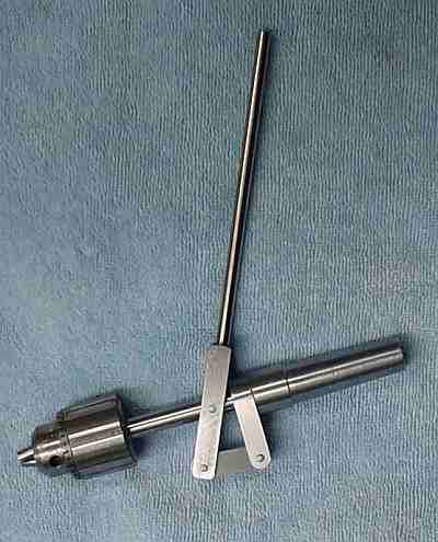
I built a copy of Chris Heapy's "Tailstock Sensitive Drill Attachment". It works well for holes within the limit of its 1 inch stroke. The chuck is a Jacobs 1/4" with JT1 taper; the 3/8 rod is small for this taper but seems to work fine so far. The MT2 was made on my taper fixture, of course, as was the JT1. This unit practically begs for a ball handle so I added one but haven't updated the picture yet.
Chris Heapy's site disappeared shortly after I built this unit so the link above goes to the Web.Archive; click on "Drawings Experimental". In the interim while Chris's site is down, I will send the DXF file I got from Chris's site if you can't get it from the above link - it is helpful to have the dimensions, saves effort thinking and experimenting.
This page was last modified by John Moran, tyro machinist and HTML tweaker. If you would like a copy of the Chris Heapy's DXF or have a comment on my site, click here, scroll down and click again.
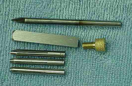
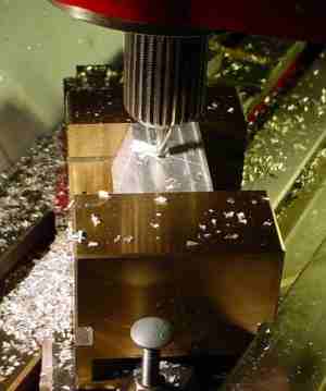
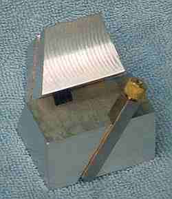
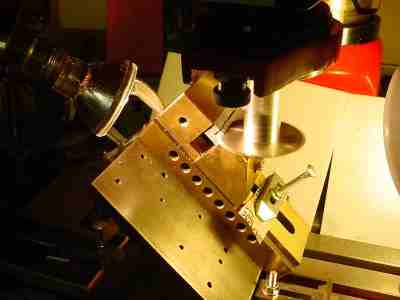
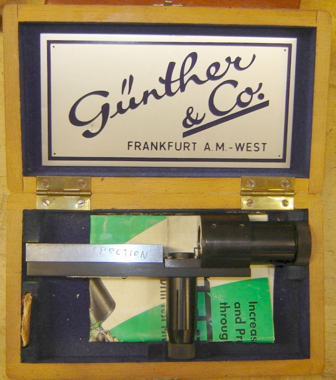
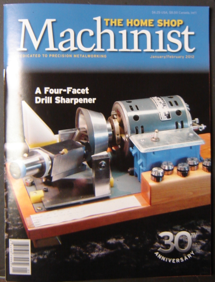
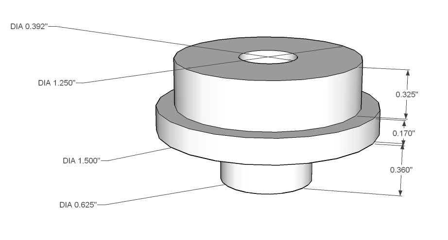
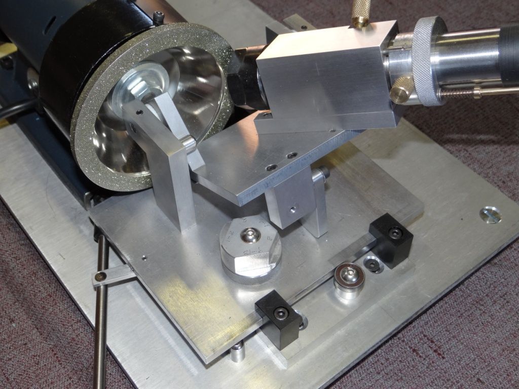
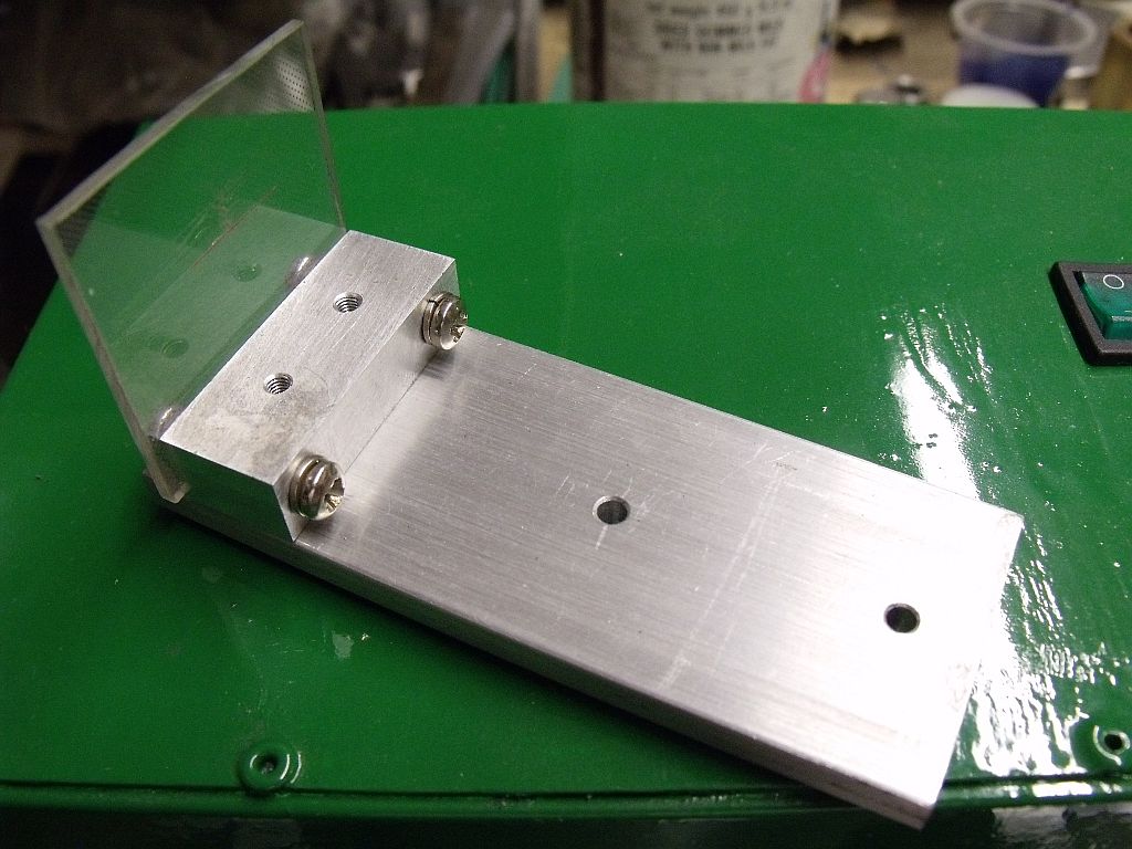
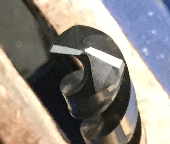
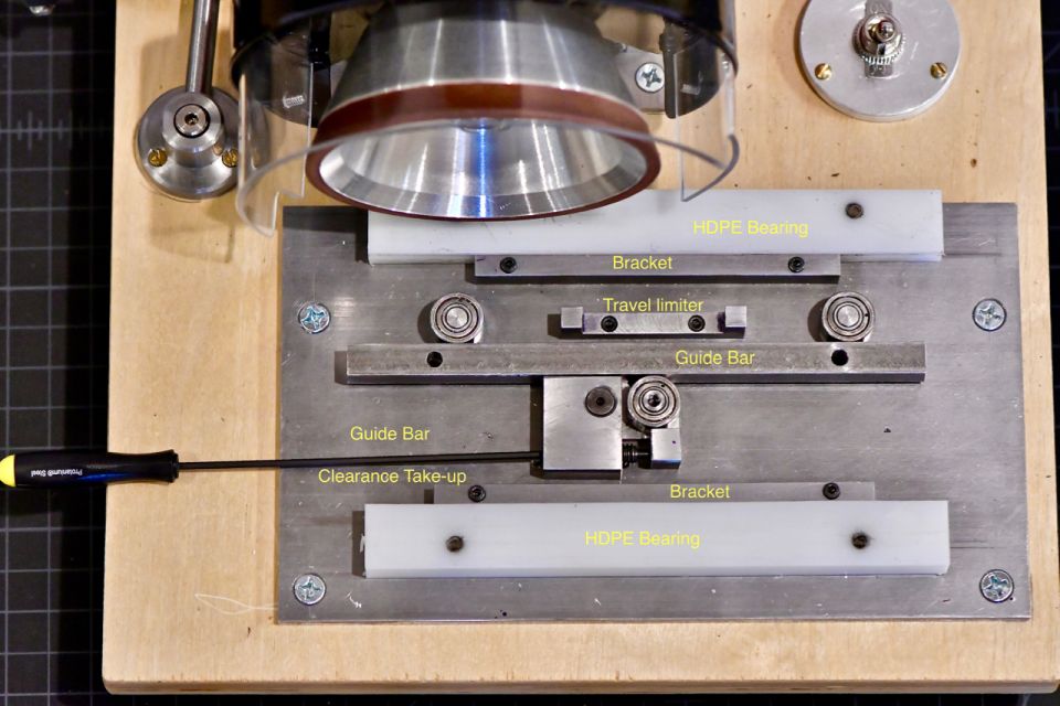
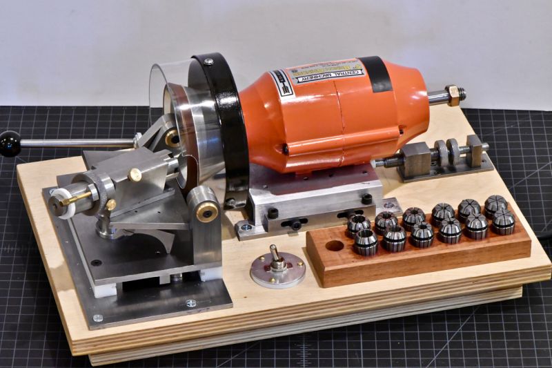