* GadgetBuilder.com *
Last Modified:
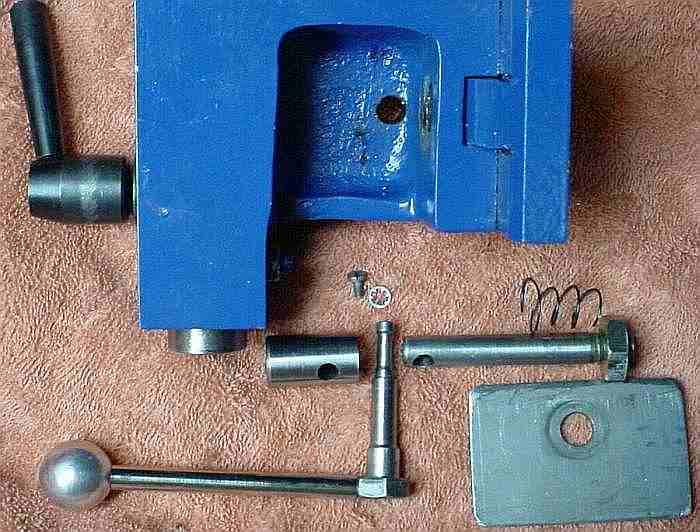
A camlock makes it much more convenient to move the mini-lathe's tailstock to clear chips when drilling deep holes. I used Rick Kruger's design, but changed it as he suggested to place the handle behind the tailstock. The main raw material for this camlock was a couple of old 3/8-16 x 3 inch bolts so the only cost was the time needed to build it. Rick's design is elegantly simple, easy to build and works very well. (LMS now offers a variation of Rick's design for $30, check it out) It is much simpler to build than most other camlocks -- no milling required -- plus, it operates smoothly with minimal force because it uses two bearing surfaces, one on either side of the cam rather than the cantilevered single bearing of most other designs. Due to the close proximity of the cam to its support bearings lighter materials are needed vs a cantilevered design.
This picture along with the information below should allow you to make a copy quickly and easily. My construction time was about 3 hours (including head scratching). There is nothing critical about the dimensions, I winged it as I went along so feel free to change things to suit the material on hand. If you've made a cantilever type camlock and would like to try this one just make a higher thimble and use a longer lock bolt (your existing lock bolt may work); it is cheap to try and easy to revert if you don't like it. Another view.
The thimble supports the lock bolt on the cam, where the thimble walls provide the two bearings noted above. It is 1 inch high and 0.590 OD (size was set by the material I had on hand which would accommodate the 3/8 lock bolt). It is drilled out to 0.365 = "U" about 0.75 deep -- it could be shorter since there is excess clearance above the lock bolt end in mine. The thimble is cross drilled 0.35 inches from the drilled end using a #1 = 0.228 drill.
The lock bolt is a 3/8-16 x 3 inch bolt. The bolt I used was rusty so I turned the unthreaded part down to 0.358 to remove the rust. Part the head off and trim the threaded end so the total length is 2.55 or a bit less; if it is too long it will hit the webs under the bed and if too short you can't get the nut on. Length isn't really critical, there is about 0.2 inches extending beyond the nut on mine; I left it long initially, then trimmed to fit during final assembly. Cross drill about 0.22 from the unthreaded end with a #1 = 0.228 drill.
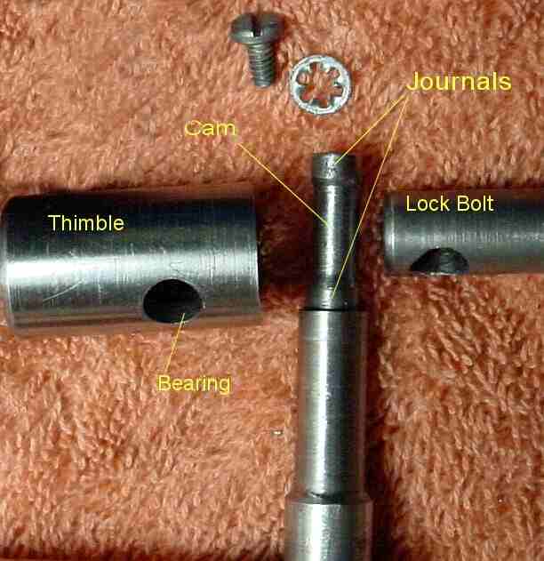 The cam is another 3/8 diameter bolt (closeup). The full 3/8 diameter extends 0.3 inch from the head; this should probably be 0.5 inch to provide a bit more clearance between the ball handle and the bump on the tailstock (the bolt might need to be longer than 3 inches to allow this). Then the diameter is reduced to 0.300 for the next 0.8 inches. Check and adjust this to match the spacing between the far side of the tailstock and the thimble; mine contacts the thimble and clears the side of the tailstock by about 0.050 to avoid binding. The cam bolt then reduces to 0.215 or so for the remainder of its length to allow it through the thimble and the hole in the lock bolt. While the threaded end is chucked, turn as much of the remaining section of the bolt as possible to 0.215, preferably enough so it can be chucked later to allow adding the cam then part it off leaving as much as possible beyond where it will be within the thimble to allow re-chucking; alternatively you could use a split sleeve to allow chucking on the 0.300 diameter section -- this is the part where us non-machinists don't know the best way to proceed so you may well have a better approach.
Before adding the cam to the 0.215 section of the cam bolt it is best to do a trial assembly so the cam can be positioned exactly where needed. First, prepare the tailstock by leveling the area around the hole in the base for the lock bolt. I found that the casting was higher on the web side of this hole so I used a Dremel with a carbide disk normally used as a saw to remove a small amount of material around the hole (i.e. to crudely spotface it). This doesn't require perfect leveling, just enough so the thimble won't tilt and bind on the cam journal. Note that there is about 10 mils clearance in the bearing to accommodate a slight mis-alignment. Once the area around the lock bolt supports the thimble in a level position, assemble the thimble and lock bolt in place on the tailstock and, using a transfer punch in place of the cam bolt, mark the tailstock web in preparation for drilling. Use packing to get the web level on the drill press table, then drill a pilot hole through the web for the cam bolt followed by drilling to 0.310 or more.
Assemble the unit with the thimble and lock bolt held in place by the cam bolt through the tailstock web. Verify that the diameter reductions on the cam bolt occur at the desired points to allow proper alignment of the parts. Mark the end of the cam bolt to allow a small extension beyond the thimble; use a file to make the pencil mark permanent.
Insert the cam bolt through the thimble and mark the cam area with a felt pen via the hole for the lock bolt. Remove the cam bolt and chuck it, then mark the cam area with shallow grooves using a pointed tool; verify that there are appropriate journal areas on either side of the cam to contact the thimble. Offset the part in the 3 jaw chuck by adding a shim of 0.040 to 0.060 between one of the jaws and the part; I used a small section cut from copper water pipe. Orient the bolt so the shimmed jaw coincides with a flat of the bolt head. Turn the cam area between the previously marked rings down until you have reduced the diameter by about 0.030 to 0.045 from its original 0.215. The tool should not touch the side where the shim is placed, just the opposite side. It takes surprisingly little reduction in diameter on one side to provide a nice cam action. I used a tool with a triangular insert to make the cam, this automatically cut a sort of chamfer into the journal area of the cam -- this to center the lock bolt on the cam without binding if it should try to wander off.
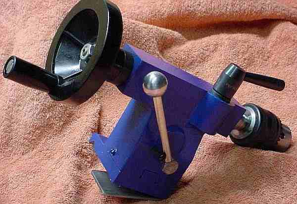
Cut the cam bolt to length per the earlier mark, drill and tap the end for a 4-40 screw and washer or alternatively leave the shaft longer and use a circlip as Rick did. I drilled and tapped the bolt head in the center of a flat to accept a 10-32, then made a handle to fit; the handle is 2.75 inches long with a 0.770 ball. I selected the flat to drill so the release position would be with the handle away from the headstock and added a 6-32 screw to the tailstock to hold the camlock handle clear of the tailstock advance knob. The handle length might well be shorter to avoid conflict with the tailstock lock handle, depending on how long you make the section of the cam bolt just under the head. Use grease on the cam when assembling.
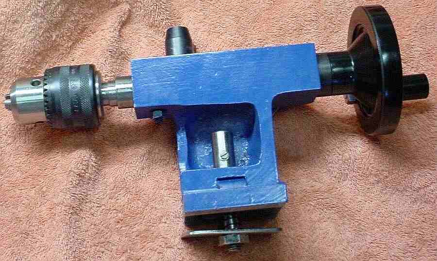
I initially used a large washer for the foot but eventually made a rectangular foot and added a small spring, both of these to make it easier to remove and reinstall the tailstock. The foot is 1/8 by 1.6 by 2.46 inches with a hole 1.2 inches from the end and 0.55 inches from the side. Round the edges and corners with a file to further ease removal and installation.
The nut on the bottom of the lock bolt may need to be faced to reduce its thickness if you use a self locking nut with a nylon insert. Adjust this nut to set the handle locking position as desired.
In use I've noticed that the cam deformed the lock bolt slightly at the top of the hole in the bolt (possibly due to the centering action from the sloped sides of the journal mentioned above). This caused a burr to protrude slightly on each side and made it difficult to withdraw the lock bolt. To avoid this, file a few mils off the side of the bolt just at the top of the hole on each side to sort of chamfer the top edge of the hole. After a couple months of use the cam and journals look polished but there are no other signs of wear. Update: after 7.5 years the deformation has not recurred and the cam continues to work well with no sign of wear.
The ways on my minilathe are thicker toward the tailstock by a few mils. I used a file on the underside of the ways where the tailstock foot contacts them to remove the paint and also to attempt to even the thickness -- this helped only slightly since the cast iron is quite hard to file. The difference in thickness is noticeable by a difference in the lock position of the camlock handle vs tailstock location on the bed. (Eventually I did fix this.)
A 1/2" long bush (with a collar on the end like an integral washer)was eventually inserted in the bottom of the tailstock base to reduce the sideways movement of the lock bolt in the hole. In addition, the area around the lock bolt where the thimble rests was milled flat, improving the result from the spotfacing done with the Dremel. The combination of these two tweaks seemed to improve repeatability of the tailstock a bit but it still is not perfect.
It is worthwhile to check the "V" for ridges and remove them if they exist -- read about ridges here.
This page was last modified by John Moran,
tyro machinist and HTML tweaker. If you have a comment on my site or its
contents, click here scroll down and
click again.