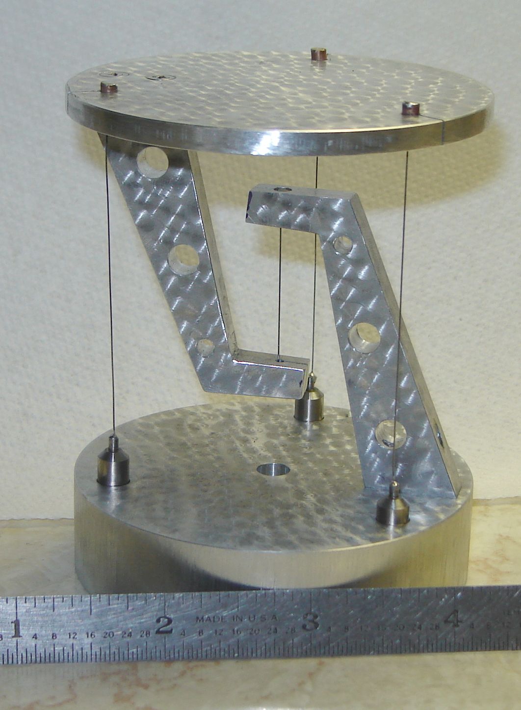
Tensegrity Table (Click to enlarge)
* GadgetBuilder.com * © 2026 by John Moran
Last Modified:
Tensegrity Table (Click to enlarge)
I watched an old video about tensegrity by Steve Mould and thought it would be interesting to make a small tensegrity table. My scrap box had appropriate sized pieces of 6061 aluminum so I was off to the shop.
The concept is straightforward: arms are fixed to the base and to the table top such that a wire in tension between these arms supports the top. Three wires tensioned between the base and the top keep the top centered over the base. These three wire lengths are adjustable to allow setting their length and tension so the top is parallel to the base. My notion was to use 0.012 music wire (guitar string) with ends soft soldered on to set the rough length and 4-40 screws for fine adjustment (crude... but much simpler to build than the commercial version shown in the video). This design isn't true tensegrity where each of the parts are purely in tension or compression - here the arms have torque applied.
The base is a 3" diameter scrap of 6061 3/4" long (which happened to have a 1/4" hole in the center). The top is a thinner bit of 3" 6061, which wound up 0.175" thick after truing. A small divot was placed in the center on the bottom of the table top. Three radii were drawn 120 degrees apart from this divot. Each radius was marked in from the outer edge enough to ensure the 0.235" (6mm) adjuster would be well in from the edge of the base, then drilled with a #32 drill (4-40 clearance). Each hole was then drilled 0.1" deep from the top of the table with a 1/8" drill to accept the 0.120" diameter brass end on the wire. A 0.014" slitting saw was used to cut along each radius from the outer edge to the hole, this to allow inserting the wire with its end soldered on.
The table top was centered on the base and they were clamped together. A #32 drill was inserted through each of the holes in the table top to mark the base. The two were separated and the base was drilled through with the #32 drill. Each hole was opened from the bottom of the base to accept the head of the 4-40 adjusting screw so it doesn't protrude. Then drill each hole out from the other side to pass the adjuster; measure carefully so 0.1" of material is left between the bolt head and the adjuster - set the depth stop on your drill press and make all the same depth so the 3 tension wires will work in any position.
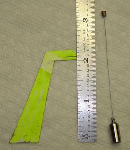 The support arm pattern was drawn on a piece of thick paper, laid out on a 1/4" thick scrap of 6061, then roughed out on the bandsaw. I bolted the arms together with a couple 4-40 flat head machine screws and finished cutting them to accurate shape in the mill. The holes for the 4-40 screws used to hold the arms together were drilled larger so both arms looked the same. The picture at right shows my pattern for the arms - much more attractive arm designs are possible but these simple arms work OK.
To ensure the arms don't interfere with the 3 tension wires, draw a diameter perpendicular to one of the radii used to locate the tension wires. Mount one arm on the bottom of the table top on this diameter using two 4-40 flat head screws, insetting the heads flush with the table top. Use a machinist square to mark the arm at the center point of the table. Remove the arm and use a #32 drill to make a hole in the center of the arm at this center point. Open the outer side of this hole to accept the end you will use on the support wire; I used 0.120" brass so drilled 0.125" diameter by 0.15" deep (ensuring the wire stop wouldn't be visible). Again, a slit is needed to allow inserting the support wire with the ends installed. I used a small insert vise to hold the arm, then held this vise in the mill's vise in the proper orientation to allow adding the slit with the 0.014" slitting saw.
Similar work is needed to add the arm to the base. To ensure the base arm won't interfere with the top's arm it is easiest to place the table top on the base with the holes for the tension wires aligned with each other. Mark the opposite end of the diameter used to position the top's arm and draw a radius on the base from this mark. Mount the base arm on this radius to ensure it is opposite the table's arm.
Five brass stops were needed from the 0.120" brass rod. The rod was end drilled on the lathe with a #60 drill as deep as I dared - it's easy to break these small drills so lots of oil and brief pecks work well. To minimize waste the five 0.125" long stops were cut on the mill using the 0.014" slitting saw with the DRO to set the length. A 1.5" length of 0.012" diameter steel wire was tinned for 1/4" on each end using NoKoRode flux and resin core solder. A brass stop was soldered to each end of the wire, passing it through the central hole; excess solder was cleaned off the end of each stop using the belt sander.
Three pieces of the 0.235" rod, 0.60" long were parted off for the adjusters. Each was turned down to 0.070" for 0.125" from one end. The resulting shoulder was chamfered at 45 degrees to within about 1/16" of the 0.070" section. The 0.070 section was end drilled with a #60 drill; this reduced section facilitates heating for soldering. The part was reversed in the chuck, drilled and tapped for a 4-40 screw (drill deep but avoid contacting the #60 hole from the other end).
Assemble the arms to their respective positions and add the center wire. Place an adjuster into one of the holes in the base. Hold the table top level in position over the base, pressing down lightly to maintain tension on the center wire, and measure the distance from the top of the adjuster to the top of the table, add 1/2" and cut 3 pieces of the tension wire to this length. Tin each end of a wire and solder one end into an adjuster; solder a brass stop to the other end of the wire. Proceed similarly with the other two wires.
To assemble, with the center wire in place lay the unit on its side and add one of the tension wires between the base and the table - I used 5/8" 4-40 screws in the adjusters. Run the screw about half way into the adjuster (NOTE: always prevent the adjuster from turning while turning the screw). Add the other tension wires similarly. Tighten the adjusters but expect them to be slightly beyond the range of adjustment. Estimate the excess length, remove the adjusters, and slide the stops down slightly by re-heating the solder. Repeat as needed until all the adjusters are in range. While doing this measure the table height at each adjuster and tweak things so the table is parallel to the base. Once it's adjusted properly remove the tension wires and use the belt sander to remove the excess wire and solder from the top of each stop.
After it was adjusted and I was sure it would stay together I took it apart and used a dowel in the drill press with some abrasive to add a random tern plate type finish. I botched the machining of the table by starting to open one of the holes for the tension wire stop from the bottom of the table instead of the top. So, the holes to hide these stops could only be drilled part way and the stops protrude rather than being hidden.
While it's a fun project to make, a couple surprising observations occur when you fiddle with the table. Flicking the table tangentially causes it to rotate slightly and continue to "shiver" radially for up to 45 seconds - not surprising, just simple harmonic motion. Lay a 6" scale on the table and repeat the experiment - the scale initially can't keep up with the rapid vibrations so it stays almost stationary while the table moves underneath it. The frictional losses rapidly damp the table movement - it slows way down in about 3 seconds - but then the rule is able to keep up with the table and they move together for quite a while, where the end of the rule makes it easier to see than watching the table. If you hold the base in your hand and flick the table the vibrations stop in about 5 seconds. Flicking the table horizontally at various points along the table arm, sometimes the vibrations seem to grow and diminish periodically; I suspect there are two motions, the horizontal rotation and a vertical movement caused by the wire tension increasing and decreasing due to the rotation. When the vertical and horizontal frequencies happen to be close together they interfere leading to the periodic change in rotational amplitude (that's my theory and I'm sticking to it).
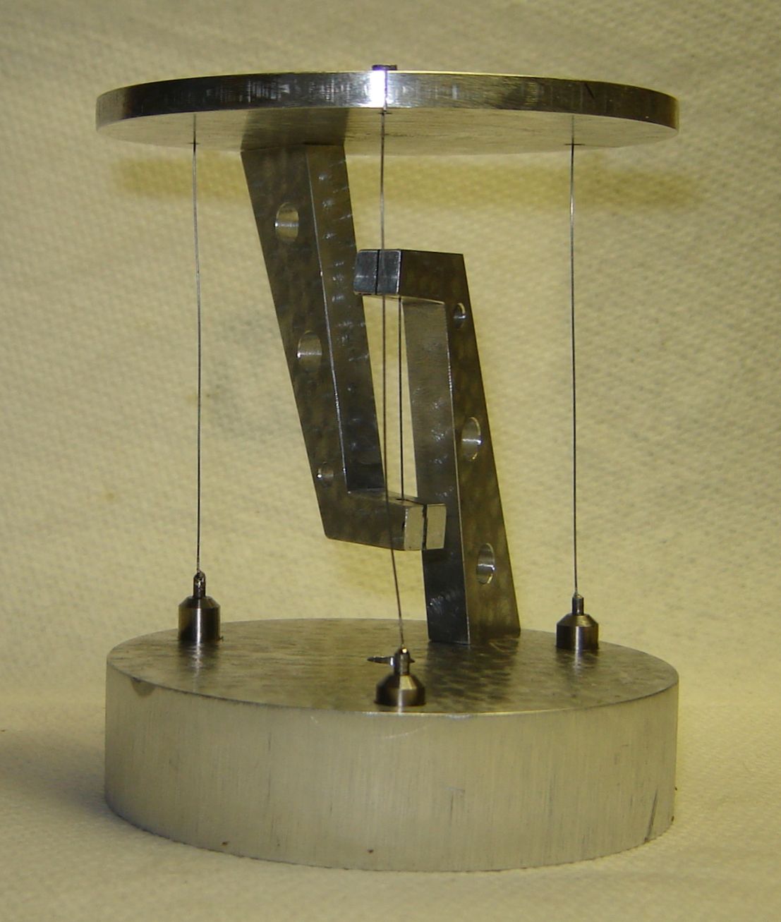 One's natural inclination is to assemble the table with the arms directly opposite each other. However it works just as well if it is assembled with the table rotated 120 degrees, as seen at right (click to enlarge).
If you have a comment on this site or its contents,
click here scroll down and click again.