* GadgetBuilder.com *
Last Modified:
Click to enlarge
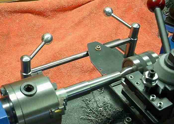
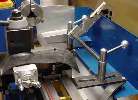
This MiniLathe taper attachment is shown here from the user's perspective. This is an adaptation of a design published in Model Engineer, May 1957; this article was available from the mlathemods3 group as LongTaper.pdf but was removed in 2007 during the Magicalia copyright flap.
The original lathe taper attachment design used a casting but the article suggested using angle iron and steel plate as a substitute. I found these materials as well as some round material at the local landfill -- the result is inexpensive but inelegant in comparison to the original as shown in the article. Mike Cox took a slightly different approach to make a removable taper attachment.
The concept is to mount a "sine bar" to the lathe bed, which bar is adjustable to set the angle of the desired taper. The cross slide lead screw is either removed or disconnected while turning tapers to allow the sine bar to control the cross slide position via a connecting part.
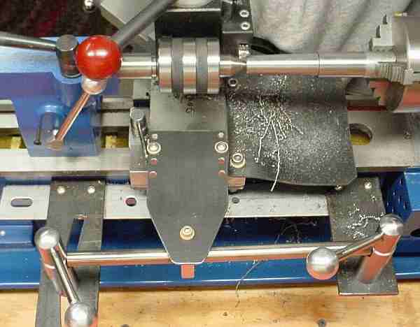
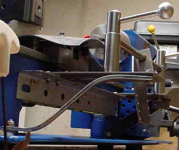
Here is a view from behind the lathe which shows more details of the construction. The taper attachment is straightforward to build but there are more pieces to it than most of my mods (none are difficult to make). This picture also shows several of the other modifications and attachments I've made for my minilathe: the tailstock camlock, the carriage lock, the Phase II toolpost, and the rubber way protector (on the chuck side of the carriage). Here is a view after adding struts to stiffen the attach scheme.
The sine bar for my taper attachment is from a discarded line printer; I cut it to length and turned a spigot on each end to fit the holes drilled in the pillars. The bronze bearing which slid along the bar in the LP was liberated from the plastic and pressed into a hole bored in the aluminum piece used to attach the bracket to the sine bar. The pillars had flats added using a fly cutter; the holes to accept the sine bar were drilled in the lathe by holding the pillars using the vise mounted in the toolpost (as shown elsewhere for milling) -- the lathe is a wonderful precision drill press when used in this manner. Similarly, the holes for the handles on the fancy nuts atop the pillars were drilled with the toolpost angled 15 degrees so the handles would angle upwards.
The ball cutter was used to put the rounded section on the top of the fancy nuts and also to make balls for the handles, of course. The ball handles are aluminum because it was on hand and also it is easier to get a good finish on aluminum than on steel. In retrospect, the fancy nuts and ball handles are very attractive (and time consuming to make) but not necessary -- regular nuts and a wrench would work too, acorn nuts would be a fair compromise. I mostly make MT2/MT3 tapers with it, so once set I seldom change it since these two have the same taper per inch. I added a witness mark to allow resetting the taper should I move it off the MT2/3 position.
The angle bracket bolts to the lathe using the holes normally used to hold the chip shield. It was placed just low enough so the bolt heads used to hold the brackets to the angle stock clear the carriage. The attachment is positioned so the tool will contact the chuck when the attach bracket is about 1/2 inch from the pillar - it would be better for indicating if placed 1/4 inch or so farther left. The pillars are 2 inches high rather than 2.5 inches - if I were to do it over again I would make them 2.5 inches since it would make it easier to fit the indicator bracket (see below) for setup. The right arm requires a slot be cut to allow adjustment; this was chain drilled and then filed -- took a while but came out nicer than expected.
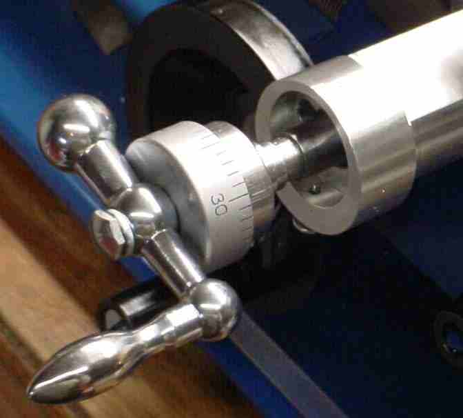 With the attachment mounted on the lathe it took 4 minutes to remove the cross slide leadscrew and attach the taper drive bracket to the cross slide. The cross slide mod simplifies disconnecting the leadscrew thus reducing changeover time by about half.
The taper attachment article didn't say how to keep the bolts inside the pillars from rotating when tightening the nuts. I cross drilled and tapped the pillar bolt on the tailstock end just above the head and inserted an 8-32 screw; this allows the bolt to rotate slightly before the screw head contacts the side of the slot. The pillar bolt on the chuck end had a round washer type area about 15 thou thick under its head; this was turned down so it was a press fit into the hole in the plate material -- this provides a friction lock which can be released by: unscrew the fancy nut about 1/2 turn, then tap it on top with your palm and rotate the bolt as needed to position the handle as desired.
Depth of cut is controlled by the compound. There are some things which weren't obvious (at least to me) about using the taper attachment. When setting the angle of the sine bar, the nut on the piece which slides on the sine bar to drive the cross slide must be loosened in addition to the two pillar nuts -- the angle of the attach piece must be allowed to change relative to the plate which connects it to the cross slide. The original lathe for which this fitting was designed had T slots; I drilled (and tapped, 10-32) holes near the end of the minilathe's cross slide, then drilled several matching holes in the attach bracket to accommodate different diameter material and compound slide settings. My QCTP conflicts with the live center and must be rotated 90 degrees for clearance when making MT2 tapers near the tailstock as shown. Any taper induced by a mis-aligned tailstock will modify the taper produced by this fixture so good tailstock alignment should be maintained - it pays to verify tailstock alignment prior to using the taper attachment.
The taper attachment worked OK the first time I tried it but then I adjusted the cross slide gibs which introduced additional friction. This caused the tool to have some hysteresis vs direction, i.e. moving right to left it cut as expected but moving left to right it was about 5 thou from the work. This was due to flex of the angle bracket from the force required to overcome friction in driving the cross slide. I eventually added struts to stiffen the support.
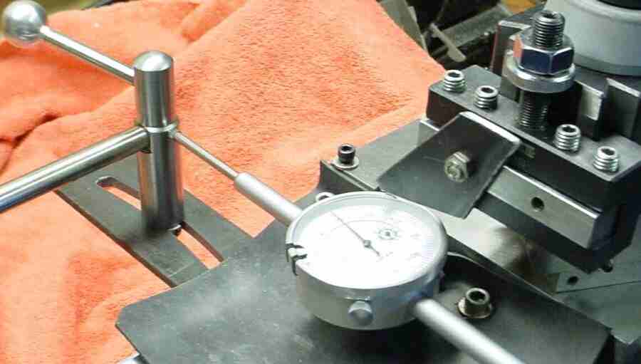
The last bit to complete the unit: a bracket to fit the toolpost which holds a dial indicator to facilitate setup. Here's another view of the bracket. This has not been used much; after roughly setting with the dial indicator I tweaked the bar to get MT2 tapers to fit an MT2/MT3 sleeve and haven't used the dial since. Looking back, I wouldn't make this bracket again - it is easy to set the sine bar using an indicator to move the carriage exactly one inch while using a toolpost mounted indicator to measure the distance to the bar: taper per inch is given in most taper tables.
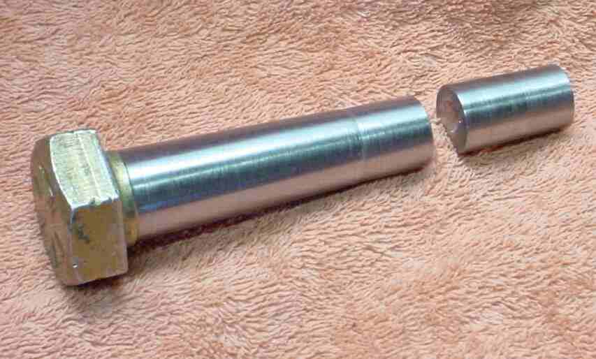
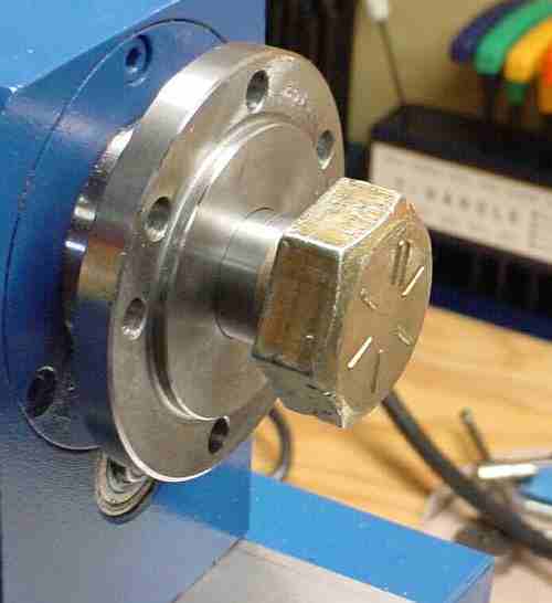
I made an MT3 center (shown with an MT2 I made) for the headstock starting with a large bolt -- the small end of the bolt wasn't quite large enough so there is a discontinuity at that end of the taper but it doesn't seem to affect it in use. I didn't use anything to hold the bolt in the headstock when turning the head down, just slapped it into the taper firmly.
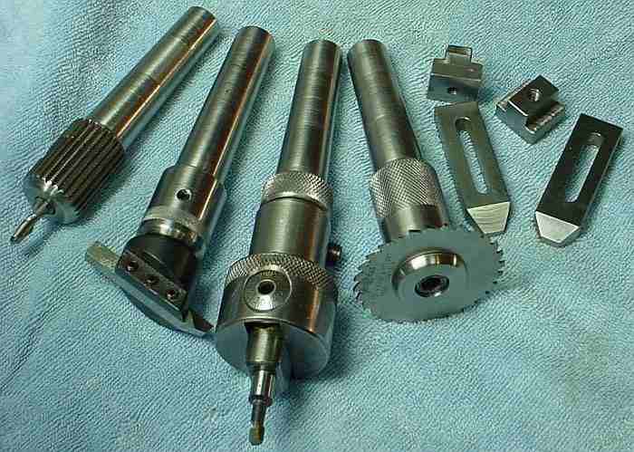
In use, after turning a taper I mark rings with a pen an inch or so from each end of the taper then make another pass to reduce the area between these marks by about 2 thou. This makes it easier to judge the fit of the taper with chalk or ink; a slight adjustment is sometimes needed to get a good fit at both ends. The reduced areas are visible on the MT3 mill tooling. I'd like a toolpost grinder for a nicer finish -- a sewing machine motor showed up at the landfill recently so it is just a matter of time and effort now :-)
A reader who made a taper attachment sent a picture and I noticed he had put the shield back on. I inquired and he sent info on how he did it (Thanks rich) so I, too, re-installed the shield and also improved the rubber protector on the cross slide. These are a real help for swarf cleanup.
Taper fit is critical to a good grip by the taper. Taper fit is more critical than most people realize, tenths make a difference here so it generally takes some work on a new taper to get a proper fit. There is enough flex in the 7x machines plus enough lack of repeatability in the tailstock position to almost guarantee that tapers produced with this attachment will require hand fitting. It takes about 15 minutes to evaluate and adjust a taper using the following technique. I use an MT3 to MT2 adapter to test MT2 tapers without removing them from the attachment -- this speeds things up considerably.
Use a Sharpie pen to draw 3 or 4 evenly spaced lines(about 1/16 wide) the length of the new taper and let the ink dry. Gently seat the taper in the socket until it just makes contact. Turn it about 1/4 turn back and forth, seated as firmly as possible without the taper locking (with a good fitting taper it can lock accidentally while doing this).
Separate them and look at the ink lines on your new taper; the ink should be wiped away at the contact areas. For good locking there needs to be good contact over about 25% or more of the area. Often, tapers are deliberately relieved in the central area (as noted above) to avoid contact; this makes it easier to achieve contact at both ends of the taper which is necessary to ensure it is properly aligned. This relief also makes evaluating the fit easier (it can be confusing on the first few).
If the contact is poor, check it again to verify your technique - it is a bit of an art to judge taper fit.
Spin the taper and lightly file the contact areas to lower them slightly, finish up with fine carborundum paper. Take off VERY little at a time, it only takes a tenth or so to change the fit considerably. Test and repeat as needed until the fit is improved.
It is fiddly work and takes some practice. If you haven't checked taper fits before then try ink on several of your tapers in turn to get a feel for what to expect when using ink to judge taper fit.
A taper may be produced by offsetting the tailstock, using ball centers in the headstock and tailstock to support the work. Or, a boring head mounted in the tailstock may be used to provide the offset. Or a simple gadget may be made that mounts in the tailstock chuck which allows offsetting a ball center. Lots of ways to accomplish mounting the work at an angle so a tool moving parallel to the bed cuts a taper on the work.
It's easier to provide this offsetting capability than to make a taper attachment, of course. What is often overlooked is that with the offset method the length of the work piece affects the taper angle. It takes a while to get the angle set exactly right so if you expect to make many tapers this is something to consider. My experience with my taper attachment is that I tweak the angle back and forth to get a good fit on MT2 which takes a while so I strongly resist changing it once it's set close enough so it is easy to do the final fitting as described above. Once set it reproduces that angle reliably. With the tailstock offset method I expect one would need to tweak the offset for each taper produced to get the angle within range for final fitting - could be slow going if you're making several identical tapers (as I did for my mill tooling).
If you have a comment on this site or its contents, click here.