
Last Modified:
A dial lock isn't a critical mod, simply a convenient alternative to the friction lock supplied with the minilathe. After seeing a plan by George Thomas describing free spinning dial locks in "Model Engineer's Workshop Manual" I converted the dials on my minilathe -- this is fairly simple once the ball bearing mods have been made. If you plan ahead (I didn't) the locks could be incorporated as part of the bearing mods.
The locks described by Mr. Thomas are more elaborate than those I implemented. In particular, his friction washer was keyed to the shaft but I found that this wasn't absolutely necessary. My dial lock parts are simple, where the friction washer could be keyed to the shaft easily by drilling a small hole in the clamp and inserting a short pin then filing a slot in the friction washer to engage this pin. Try it without the pin and if needed add it later -- I originally planned to do this but found it worked fine without a pin.
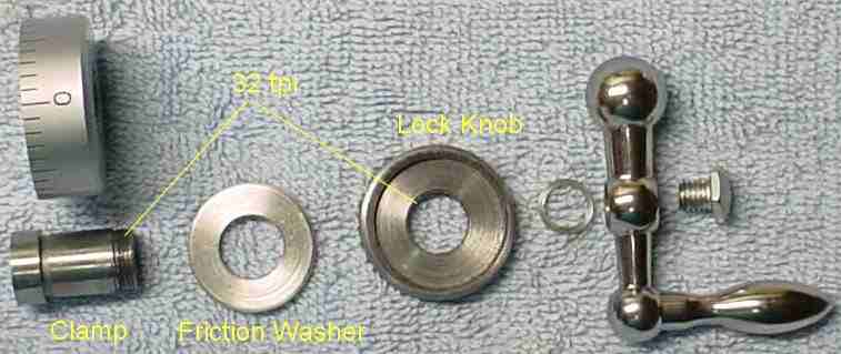
The steel lock knob is effectively a lightly knurled round nut, 0.200 inches thick with a 32 tpi thread in the central hole. One side is bored out 0.070 deep to accept the friction washer. The aluminum friction washer is sized to fit into this bore and is 3-5 mils thicker than the depth of the bore so that it protrudes from the lock and contacts the dial when the lock is actuated. A thin friction washer could be used by decreasing the bore depth but the thick one simplifies adding a pin to keep it from rotating should this be deemed necessary.
The original shaft was machined to accept the clamp shown in this picture; the clamp looks just like the area removed so it works like the original except the assembly can be removed with the friction spring remaining in place. This clamp was then replaced with the threaded clamp shown here i.e. the change was done so recovery is easy if things don't go well. The width of the shoulder on this clamp should be set to make the dial clear the spacer by a couple of mils. I made the overall clamp too short so the compound's handle conflicted with the dial lock; making a little washer (shown between the handle and dial lock) solved the problem -- if you allow for the shape of the handle this won't be needed. The lock washer was eliminated and the bolt head was rounded to increase knuckle clearance.
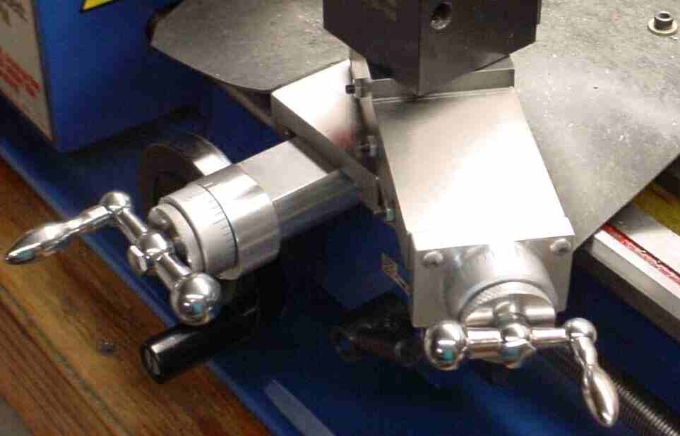
This picture shows both dial locks. The clamp on the cross feed was extended to accommodate the lock, leaving less of the shaft within the handle -- if planned for, the shaft extension and bolt could be made longer. On the compound, the thick washer between the dial and the handle is replaced by the dial lock. The dial lock is smaller diameter (1.13) than the dial to avoid conflicting with the ball on the end of the handle.
The picture shows the parts for the compound lock. The cross slide lock concept is the same except the clamp is slightly different.
The locks open or close by turning about 90 degrees. When open, the dial spins freely. In the locked position the dial is solidly clamped to the shaft but without the pin to the shaft, a firm grip on the dial and a good ccw twist can open the lock.