* GadgetBuilder.com *
Last Modified:
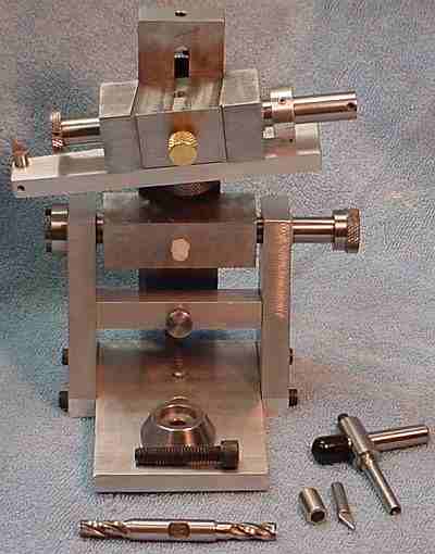
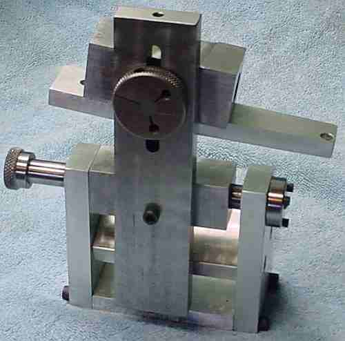
The Mini-Tinker is a version of the Tinker Tool and Cutter Grinding Jig whose plans are sold by Guy Lautard. Plans and information for a very similar jig, the Raymac, appeared in Model Engineers Workshop serialized 9/2001 to 2/2002; this unit may be somewhat more capable than the Tinker. The jig holds the tool to be sharpened and allows applying it to a bench grinder wheel in a precise way. After studying the plans I decided to make a Mini-Tinker instead of the standard Tinker but scaled up the size of some parts to eventually allow sharpening cutters of 1/2 inch or more. Initially, I made the normal Mini-Tinker tool holder which is limited to cutters with shanks of 3/8 inch or less but I have the material for a larger tool holder block to be built after trial of the regular size block. Here is the back side. (Eventually I decided the Mini-Tinker wasn't for me and built a Brooks-Stent which has worked out well.)
The Tinker is simpler than other cutter grinders (like the Stent and Quorn) and the Mini-Tinker is a further simplification of the underlying Tinker design. The difference is that the Mini-Tinker does not allow complete freedom in selecting the relief angles used in sharpening the teeth of end mills -- standard angles of 7 and 15 degrees are built in. The plans indicate these are the default angles used in most end mills so this suits my needs and makes it simpler and less error prone (for us absent minded types) than a jig where each of the angles must be selected and set each time a cutter is sharpened. Likewise, the slight angle where the outside of end mill blades are lower than the inside is fixed. This intelligence about how an end mill should be sharpened is built in via the wide slots milled into the tool holder block (the upper block in the picture); this block is rotated to select the appropriate slot for the part of the end mill being sharpened. Not all grinding angles are fixed so there is a setting gauge for the side (flute) relief angles plus an adjustment to set the centermost point to grind. I've only sharpened one end mill so far but this cutter, which was in poor shape, now seems to work fine. Lautard suggests MT2 collets to hold tools within a toolholder made from large drill rod; I expect to make multiple toolholders from drill rod instead because it is simpler and cheaper, mainly because I use only a few shank diameters.
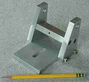
Construction was not particularly difficult, possibly because I used a different (simpler) method to avoid the boring operations suggested in the plans to ensure alignment of the journals and bearings. The base is the first section constructed. The large holes are then fitted with plastic bearings: teflon, nylon, or delrin will do. The pivot shaft is 1/2" drill rod and the holes in the base are 5/8. The base sides were rectangular pieces initially so I marked out the position of the holes to be drilled on one side piece. I drilled the holes in the base sides for the cross piece and tapped the holes in one side, drilled clearance holes for these two in the other side and then used 10-32 bolts to hold the side pieces together. The other holes were then drilled and the large holes were bored to size on the mill. The edges of the sides were also fly-cut while bolted together, thus ensuring they were identical; although this wasn't really necessary it was easy to do once they were bolted together.
The base was carefully spotted to the sides, d/t 10-32 for bolting the sides to the bottom. Delrin bearings were turned with a slight taper in the outside so they would just start into the large holes bored in the base sides. The center of these bearings was bored to 0.488. The bearings were installed with a rubber mallet -- no epoxy or Loctite was necessary. One side was bolted to the base. The shank of a 1/2" reamer was put through and the other side of the base was installed with the reamer trapped between the sides; the cross piece was also installed. Masking tape was wrapped around the shank of the reamer where it touched the bearing to ensure it was centered and the opposing bearing was hand reamed, which allowed the reamer to be extracted from the base. The reamer was turned around and run through the bearing by turning it backward (not allowed in a metal bearing but the plastic bearing didn't hurt my reamer) and then the second bearing was reamed in the same manner. This simple scheme resulted in good alignment of the bearings with no need for line boring. The base sides were not removed after completion of reaming lest the bearing alignment be disturbed. The bearings were tighter than desired so the reamer was run through a couple times.
The tool holder block was done differently than the plans called for, instead adapting the method used for aligning the base bearings. The block was drilled from both ends on the mill/drill and the hole was enlarged by drilling and then a 1/2" end mill was run in -- the end mill corrected any meandering by the drill. This hole was bored to 0.520 and then the ends were bored to 0.625 for 1/2 inch using a boring head in the mill. A delrin bearing was installed in one end; a short section of the bearing material was bored to fit the reamer shank and used to maintain alignment of the reamer while reaming this bearing. The second bearing was then installed and masking tape was placed on the reamer shank (as in aligning the base bearings) to ream the second bearing. The 1/2" tool holder (made from drill rod) was tried and the reamer was run through the delrin bearings several times to obtain a low friction but shake free fit.
The first item I added to the Tinker tooling is a holder for the diamond used to true the wheel (shown at lower right in the picture). As usual this was made from mystery metal in my junk box; a 1/2" piece (which had a 1/4" spigot already) was cross drilled and then a 3/8 end mill was run through followed by a reamer. A set screw in the end retains the diamond holder's 3/8 shank. The Tinker's controls allow nice fine adjustment for truing the wheel -- the 90 degree fitting allows truing the wheel's face and inserting the diamond holder alone allows truing the side of the wheel. I sharpen drills on the side of the wheel using a Pit Bull sharpener but hadn't had a way of cleaning and truing it previously. The amount of material removed from the wheel was small, under 5 thousandths, but it produced noticable dust in the process; next time I'll cover the Tinker with damp paper towels to minimize cleaning effort. In addition, I think a rubber shield could be added to help protect the Tinker from abrasive dust so that's on my long (and growing) to-do list.
I find it helpful to remove the toolholder to judge progress on the tool being sharpened. When sharpening the helical flutes of 3/8 end mills, the knob on the toolholder prevents the toolholder from passing the toothrest finger (see the picture above). This prevents removing the toolholder unless the toothrest bracket is loosened, which changes the setup and requires re-setting. (The knob is needed on the 3/8 end to provide threads for the set screw.) The solution is to use a larger guideblock/toolholder so that a toolholder knob is not needed; the toolholder can then be withdrawn through the guide block (not possible with a knob installed). The regular toolholder can be withdrawn through the guideblock when sharpening 1/4" tools because the knob is on the right.
The bench grinder used with the MiniTinker (or any similar sharpener) must be high quality with a well balanced wheel. Any vibration from the grinder will cause the sharpened edge to be slightly irregular. My bench grinder vibrates so I plan (eventually) to make a precision arbor for use with the Tinker.
The Mini-Tinker works well for making D bits and similar tools. It allows grinding the end to half diameter in an nicely controlled way and then, after re-setting, will grind the compound angled end to provide relief in both directions. Prior to the Mini-T, I had not been able to make a really satisfactory D bit. Countersinks are also feasible. End mills have been a problem for me.
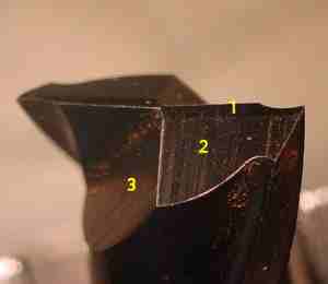 The picture shows a new 2 flute end mill (with some of the protection still adhering); the primary clearance angle is marked "1", secondary clearance is marked "2" and the third clearance is marked "3". I measured angles on this cutter for these clearances as: 10, 21, 45 degrees - where the 45 degree angle is rotated to a different position. The Mini-Tinker has slots in the side of the tool block where it mates with the standard which set angles of 7 and 15 degrees for the primary and secondary clearance angles; the Tinker allows adjusting these angles -- the instructions recommend using 7 and 15. These angles likely work fine but they are not the angles found on any cutters I have purchased. As near as I can tell from Lautard's instructions, there is no provision for grinding the third clearance angle using either the Tinker or Mini-Tinker. Without the ability to grind this third clearance angle, I haven't figured out how to do more than touch up an end mill.
As a neophyte Mini-Tinker user, I very lightly touched up a couple of slightly dull end mills by grinding only the primary clearance and was happy with the performance. However, I have been unpleasantly surprised by the results of attempting to restore cutters where the tip of a tooth is chipped or heavily worn. In this situation, the land for the primary clearance widens from grinding so the secondary clearance must be ground also. However, when the secondary clearance is ground the center of the cutter widens; apparently, the third clearance angle needs to be ground too in order to accommodate grinding of the secondary clearance and I expect the angle of cutter rotation when re-grinding this angle needs to change too because the helical flutes have been shortened. (See Gashing using the Brooks.)
There is a possibility that I'm doing something wrong because in addition, the "dish" to the end teeth which causes the outer end of the teeth to be a couple of thou lower than the inner end isn't there, i.e. the cutter end is flat. I checked the slot in the tool block for the depth difference from side to side and it is machined correctly so I added a couple of strips of masking tape on the shallow side to make it even shallower with no apparent result. I find this puzzling because the geometry intuitively looks correct so that it should work but the results don't agree. The geometry is confusing because there are several slight angles included plus the movement of the tool is an arc rather than a straight line so it is hard for me to get it all straight in my mind.
My Mini-Tinker did not produce the expected relief angle on the helical edge of an end mill when I calibrated the setting gage as specified in the plans. The relief angle is also very dependent on the rotation angle of the cutter as set by the finger and this is difficult to judge accurately while using the MiniT -- a likely cause for this problem.
Bottom line: The Mini-Tinker, at least in my unskilled hands, won't sharpen end mills -- the primary reason I built it. It is handy for D bits and counter sinks but I don't make enough of these to justify the effort I put into construction. Eventually I gave up on it and built the Brooks-Stent.
I believe the MiniTinker base, with some modification, will be adequate for use with the regular Tinker guideblock/toolholder. I like the MiniT base better than the Tinker base because the standard is supported between two bearings rather than cantilevered from a single bearing -- a matter of taste. I have been doing other things so I haven't made a regular Tinker guideblock/toolholder to fit my MiniT base. The base was initially made larger than called for in the plans so it should be possible to do this in the future. The stop used to limit rotation doesn't work well in that it is not precise -- it moves slightly from loosness in the thread.
The width of the bottom plate on my Mini-Tinker was increased from 2 inches to 3 inches. The width of the standard was increased from 0.75 inch to 1.5 inches. The pivot block length was increased from 1.75 inches to 2.75 inches. The guide block was increased from 2 inches to 2.75 inches (the Tinker guide block is 3 inches).
A machinist might complete the Mini-Tinker in about 20 hours; it took me over 30 hours plus time to study the plans. The plans are partly drawings but much information must be extracted from the instructions for the regular Tinker. The nature of the documentation would make construction more difficult for builders who are not fluent in English.
If you have a comment on this site or its contents,
click here.