* GadgetBuilder.com *
Last Modified:
The cross slide travel on my minilathe needed to be increased to accommodate the Phase II toolpost since the size of this toolpost constrains the diameter which may be turned. In addition, the cross slide was "notchy" on my lathe so I wanted to add a ball bearing as part of the cross slide mod. And, I wanted to simplify disconnecting the cross slide lead screw to make it easier to use the taper fixture while keeping the full range of travel required to use the ball fixture.
The mini-lathe cross slide mods available on the net seemed too complex for my meager machining skills so I arrogantly decided that I'd do it more simply. Now that it is working I like the result and it is conceptually simpler than the other designs but I found it more difficult to machine than prior mods I've made. I failed to plan the order of machining operations for the spacer, making it more difficult than it should have been. Overall, a humbling experience which fortunately works fine - there was a point where I thought it might wind up as scrap.
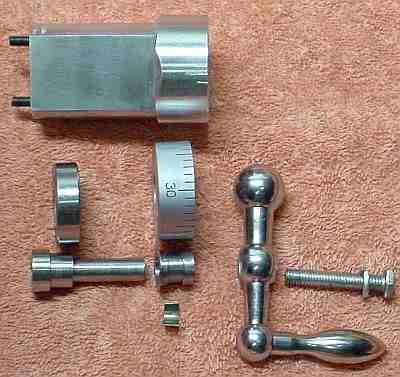
The goal was to increase travel of the cross slide toward the operator while preserving the original travel limit away from the operator; this to accommodate use of the ball fixture which needs to be at the lathe centerline, very near the original away limit. The design concept is to simply add an extension on the handle end of the shaft to accommodate the increased travel allowed by removing material from the carriage as suggested by Gordon Scott; Gordon's mod moved the leadscrew and thus the range toward the operator but didn't increase the available travel. Adding a shaft extension requires a longer spacer and as part of the mod I included a ball bearing in this new spacer. The original lead screw is only about 30 mils closer to the operator once the mod is completed, this in order to ensure that the shoulder on the shaft doesn't foul the carriage. The picture shows the old spacer next to the new setup. Note that only the carriage is changed; all other original parts are un-affected so the lathe may be returned to its original configuration easily if desired.
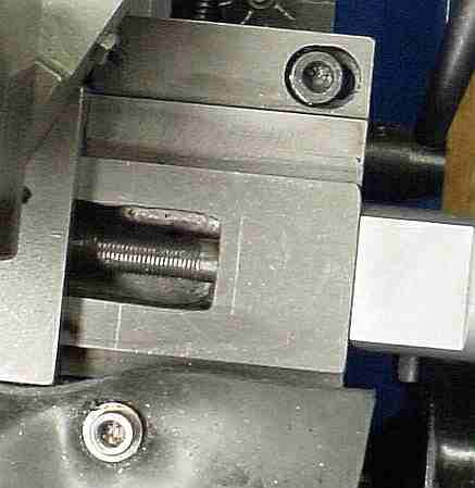
The first step was to hog out the carriage to allow increased cross slide travel; as shown here, there was an additional 5/8 inch of thread on the lead screw which became accessible once the material was removed. Since I don't have a mill, I set the depth stop on the drill press and chain drilled with a 1/8 drill around the area to be removed, then drilled as many holes as possible in that area. A carbide rotary rasp in the drill press was used to take out the remaining material followed by the Dremel to clean up the corners - the rotary rasp worked amazingly well, the result looked similar to milling. Cast iron is messy but soft.
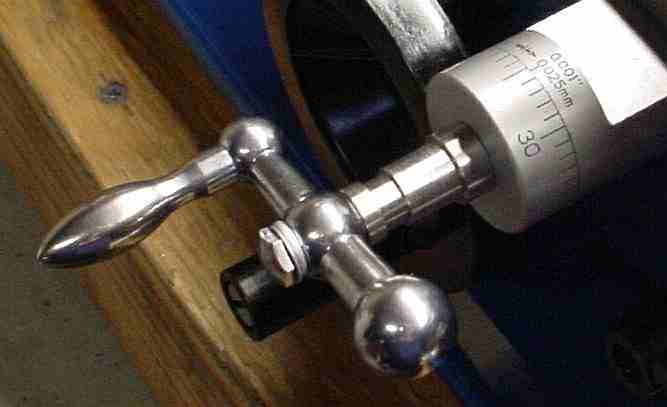
Next step was the shaft extension. Initially, this was just like the end of the original shaft except that the inside end was a nice fit over the end of the original shaft. A metric bolt was cut to length and the head was rounded in the ball fixture to a pleasing shape. When bolted in place as shown it worked fine and showed that the shaft extension concept was workable. At this stage I was trying to copy the idea in the compound slide of using the dial to transfer thrust to the handle; this proved unworkable with the ball bearing because the clamping pressure needed on the bearing inner race locks the dial to the handle. Eventually I figured out that the backlash in the compound was there for a reason and re-worked the shaft extension appropriately.
The spacer was the only difficult part to machine (see the retrospective below for thoughts on making it easier). In order to retain the bearing's outer race I needed additional material below the bearing. Using some available 1.5 inch aluminum round I placed the shaft off center so that the rim of the dial would be even with the top of the material. This meant that to align the round I had to adjust the 4 jaw to center the dot marking the desired hole then run the dti along the length of the round to determine whether it was tilted, rotate it 90 degrees, check again for tilt, adjust any tilt out, then re-adjust to center the dot (which moves when adjusting for tilt), etc. this went fine for the large hole for the shaft. Then, I turned the outside concentric with the shaft to match the diameter of the dial except the area on the end which holds the bearing and is the stop for the slide. I went through the centering process for the two holes to hold the retaining screws, the whole deal of centering the dot, adjusting the tilt to zero, etc. There must be a better way of setting this up but as a neophyte this was the best I could figure. Since any small mis-alignment of the holes would be a problem if it occurred on the end which contacts the carriage, I drilled from that end to ensure the holes would match. This meant that I couldn't counterbore to let the heads of the retaining screws in at the same time that I drilled the original holes. I figured that I'd just counterbore with the drill press since it needn't be quite as precise as the hole placement. However, the holes were so close to the center hole that they broke through causing the drill to move toward the center hole more than an acceptable amount. This was the point where I thought it was scrap but I rescued it using the Dremel for some frantic rasping to get the counterbore to match the hole. Not pretty but it worked out. A fly cutter was used to flatten the top of the spacer. After all this, I still don't know how to actually make this part efficiently using the tools I have although I would drill and counterbore the retention bolt holes prior to the center hole if starting over. Life is tough for non-machinists using a lathe!
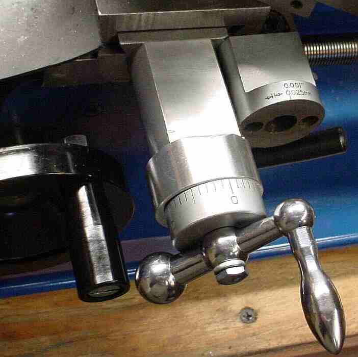
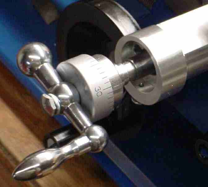
After the spacer fiasco I was really unhappy when the dial didn't work. It was quick to fix by turning the extension down to remove the part which holds the dial, them making a part to go over the shaft and hold the dial plus clamp the inner bearing race - note the thin flange on the inner end of the clamp piece. The overall parts lineup (with the dial backwards, unfortunately) should make the setup clear. Here's a second picture which shows the bearing end of the spacer. I was going to use a different method of retaining the bearing shell but the set screw was easy, works well and hasn't affected smoothness of the bearing; the bottom of the spacer could be slit and used as a real clamp via a screw across the bottom if the set screw is unacceptable.
To disconnect the lead screw while turning tapers: wind the cross slide fairly far back, loosen the set screw which retains the bearing, and pull the cross slide toward you to move the bearing away from its pocket as shown here. If desired the lead screw could now be removed easily (not necessary for normal tapers). In order to allow this the shoulder on the lead screw shaft must be turned down slightly so it will clear the heads of the retaining screws and the center hole in the spacer must be made large enough to pass the (now smaller) shoulder on the lead screw shaft. The shoulder could be removed completely but this would preclude returning to the original cross slide setup.
The result is amazingly smooth rotation of the cross slide shaft along with the desired 5/8 additional travel. There was a bit over 1 mil of backlash remaining in the cross slide (but keep reading); this may be due to axial play in the $0.72 ball bearing. I considered adding a plate across the far end of the cross slide with a pointed bolt to contact the center hole on the end of the cross slide lead screw to provide an adjustable pre-load. After further thought, I realized it takes more than a simple plate because the brass nut extends beyond the end of the cross slide when using the ball cutter. More importantly, I found that the brass nut wears fairly rapidly when adjusted for minimum backlash and increases the backlash to about 4 mils - rather than re-adjust this nut frequently, I live with it. It doesn't make sense to pre-load the bearing when the brass nut is the primary source of backlash. Update: I did the Split Nut Mod to reduce backlash.
An unanticipated benefit of lengthening the cross slide spacer is that it reduces the frequency of bumping the cross slide handle while winding the carriage handle. To eliminate this completely I shortened the handle on the carriage drive by about 1/2 inch, not shown because it was done after taking the pictures. A further apparent benefit of this cross slide mod is that parting off seems to work much better, i.e. chatter and/or digging in while parting is almost eliminated where it used to be common. Perhaps my technique has improved or possibly the cross slide gibs are now tighter because the lead screw friction is lower; at any rate, parting is much less chancy.
One interesting point to this project is that I have never understood how it is possible to tighten the bolt which holds the knob on the cross slide since you can't hold the shaft to keep it from turning except by the knob which isn't tight (yet). And still, it works. This design takes that one step further because the knob is on the extension, not the shaft the bolt is threading into. Magic!
In retrospect, the shaft extension seems to be a fine way to accomplish this mod but the bearing choice was not the best. The 6001-2RS bearing was selected because its 12mm bore fits the shaft of both the compound and cross slide. This caused me to add the enlarged section on the outboard end of the spacer which made gripping and centering the work much more difficult. Using a 608-2RS bearing would make this whole project much easier since it is much smaller. The 8mm bore would fit onto the extension shaft nicely by simply using a smaller diameter section where the bearing fits. Most important, the spacer could be turned to match the diameter of the dial with no eccentric section needed since there would be enough material around the bearing for the set screw; this would make centering for drilling and boring MUCH easier plus the spacer could be reversed in the chuck without the awkwardness caused by the eccentric on the original design. Overall, I think it would be considerably easier to machine than my original design. Another thing to consider would be to make the hole for the shaft smaller; I made it large (to allow the shoulder on the lead screw which retains the shaft with the original spacer through) so the spacer can be left in place when removing the shaft-- if you don't mind removing the spacer to get the shaft out (or you're willing to remove the shoulder once everything is working) then the smaller hole will avoid the problem of the holes running together. Experience is a hard teacher and there might be more to learn by re-doing this project with this revised approach but the one I built works fine so I'm done -- any takers on the 608-2RS design?
Skatebearings (who supplied my bearings) no longer carry the 608-2RS but they are available on eBay, currently 8 for $8 delivered. In fact, only 3ea of the 608-2RS bearings are needed to do both slides and have a spare on hand.